15.2 Boolean Algebra & Logic Circuits
A Level · 33 questions found
What this topic covers
Section titled “What this topic covers”- Truth tables for complex circuits including half-adders and full-adders
- Flip-flops (SR, JK): draw circuit, derive truth table, use as data storage
- De Morgan’s laws: understand, apply and use to simplify
- Simplify logic circuits/expressions using Boolean algebra
- Karnaugh maps (K-maps): purpose, benefits and solving logic problems
Past paper questions
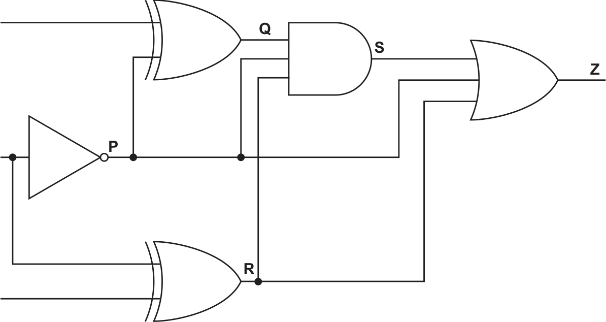
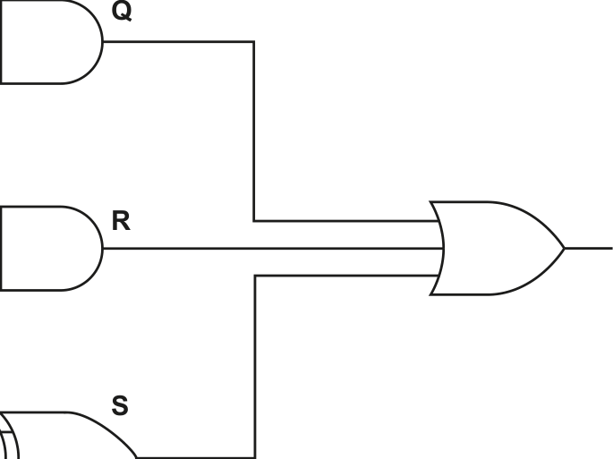
Section titled “Past paper questions”(a) The diagram shows a logic circuit. 3 marks
| Q | ||
| Q | ||
Complete the truth table for the given logic circuit. Show your working.
| Working space | |||||||
|---|---|---|---|---|---|---|---|
| A | B | C | P | Q | R | S | Z |
| 0 | 0 | 0 | |||||
| 0 | 0 | 1 | |||||
| 0 | 1 | 0 | |||||
| 0 | 1 | 1 | |||||
| 1 | 0 | 0 | |||||
| 1 | 0 | 1 | |||||
| 1 | 1 | 0 | |||||
| 1 | 1 | 1 |
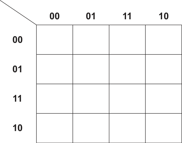
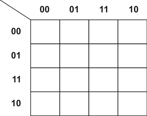
(b) (i) Complete the Karnaugh map (K‑map) for the Boolean expression: 2 marks
A.B.C + A.B.C + A.B.C + A.B.C
| BC | ||||
|---|---|---|---|---|
| 00 01 11 10 0 1 |
00 01 11 10 0 1 |
00 01 11 10 0 1 |
00 01 11 10 0 1 |
00 01 11 10 0 1 |
| 00 01 11 10 0 1 |
||||
| 00 01 11 10 0 1 |
(ii) Draw loop(s) around appropriate group(s) in the K‑map to produce an optimal sum‑of‑products. 2 marks
(iii) Write the Boolean expression from your answer to part b(ii) as a simplified sum‑of‑products. Do not carry out any further simplification. 2 marks
Show mark scheme
6(a) [3 marks]
One mark for working, (all four columns P, Q, R and S) One mark for first four rows of column Z One mark for second four rows of column Z Working space 0 0 0 1 1 1 1 0 0 0 1 1 0 1 0 0 0 1 0 1 1 1 1 1 0 1 1 1 0 1 1 1 1 0 0 0 1 1 1 0 1 0 1 0 0 0 1 0 1 1 0 0 1 1 1 1 1 1 1 0 0 1 1 1
6(b)(i) [2 marks]
Two marks if no errors present One mark if only one error present BC 00 01 11 10 A 0 0 0 1 1 1 0 1 0 1
6(b)(ii) [2 marks]
One mark for each correct loop (Max 2) BC 00 01 11 10 A 0 0 0 1 1 1 0 1 0 1
6(b)(iii) [2 marks]
One mark for each mark point ( Max 2 ) • One correct Boolean term with a + / OR sign • All Boolean terms and operators correct and no other terms present A.B + B.C + A.B.C
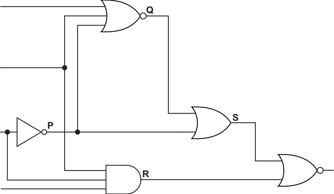
(a) The diagram shows a logic circuit. 3 marks
Complete the truth table for the given logic circuit. Show your working.
| Working space | |||||||
|---|---|---|---|---|---|---|---|
| A | B | C | P | Q | R | S | Z |
| 0 | 0 | 0 | |||||
| 0 | 0 | 1 | |||||
| 0 | 1 | 0 | |||||
| 0 | 1 | 1 | |||||
| 1 | 0 | 0 | |||||
| 1 | 0 | 1 | |||||
| 1 | 1 | 0 | |||||
| 1 | 1 | 1 |
(b) (i) Complete the Karnaugh map (K-map) for the Boolean expression: 2 marks
A.B.C + A.B.C + A.B.C + A.B.C
| BC | ||||
|---|---|---|---|---|
| 00 01 11 10 0 1 |
00 01 11 10 0 1 |
00 01 11 10 0 1 |
00 01 11 10 0 1 |
00 01 11 10 0 1 |
| 00 01 11 10 0 1 |
||||
| 00 01 11 10 0 1 |
(ii) Draw loop(s) around appropriate group(s) in the K-map to produce an optimal sum-of-products. [2]
(iii) Write the Boolean expression from your answer to part b(ii) as a simplified sum-of-products. Do not carry out any further simplification. 2 marks
Show mark scheme
6(a) [3 marks]
One mark for working, (all four columns P, Q, R and S) • One mark for first four rows of column Z • One mark for second four rows of column Z Working space 0 0 0 1 1 0 0 1 0 0 1 1 1 1 1 1 0 1 0 0 0 1 0 1 0 1 1 0 0 0 0 0 1 0 0 1 0 0 0 1 1 0 1 1 0 1 0 1 1 1 0 0 1 1 0 1 1 1 1 0 1 0 0 0
6(b)(i) [2 marks]
Two marks if no errors present One mark if only one error present BC 00 01 11 10 A 0 0 1 1 0 1 0 1 0 1
6(b)(ii) [2 marks]
One mark for each correct loop (Max 2) BC 00 01 11 10 A 0 0 1 1 0 1 0 1 0 1
6(b)(iii) [2 marks]
One mark for each mark point ( Max 2 ) • One correct Boolean term with a + / OR sign • All Boolean terms and operators correct and no other terms present _ _ _ A.C + B.C + A.B.C
(a) The Karnaugh map (K‑map) represents a logic circuit with four inputs.
| AB | ||||
|---|---|---|---|---|
| 00 01 11 10 00 0 0 0 0 01 1 1 1 0 11 0 1 1 1 10 0 0 1 1 |
00 01 11 10 00 0 0 0 0 01 1 1 1 0 11 0 1 1 1 10 0 0 1 1 |
00 01 11 10 00 0 0 0 0 01 1 1 1 0 11 0 1 1 1 10 0 0 1 1 |
00 01 11 10 00 0 0 0 0 01 1 1 1 0 11 0 1 1 1 10 0 0 1 1 |
00 01 11 10 00 0 0 0 0 01 1 1 1 0 11 0 1 1 1 10 0 0 1 1 |
| 00 01 11 10 00 0 0 0 0 01 1 1 1 0 11 0 1 1 1 10 0 0 1 1 |
0 | 0 | 0 | 0 |
| 00 01 11 10 00 0 0 0 0 01 1 1 1 0 11 0 1 1 1 10 0 0 1 1 |
1 | 1 | 1 | 0 |
| 00 01 11 10 00 0 0 0 0 01 1 1 1 0 11 0 1 1 1 10 0 0 1 1 |
0 | 1 | 1 | 1 |
| 00 01 11 10 00 0 0 0 0 01 1 1 1 0 11 0 1 1 1 10 0 0 1 1 |
0 | 0 | 1 | 1 |
(i) Draw loop(s) around appropriate group(s) in the K‑map to produce an optimal sum‑of‑products. [3]
(ii) Write the Boolean expression from your answer to part a(i) as a simplified sum‑of‑products. 2 marks
Do not carry out any further simplification.
(b) Simplify the following expression using De Morgan’s laws and Boolean algebra. 3 marks
Show all the stages in your simplification.
X = A+B+C+B+C
Show mark scheme
6(a)(i) [3 marks]
One mark for each correct loop (Max 3) 00 01 11 10 00 0 0 0 0 01 1 1 1 0 11 0 1 1 1 10 0 0 1 1
6(a)(ii) [2 marks]
One mark per mark point ( Max 2 ) MP1 One correct Boolean term with an OR sign MP2 All three correct Boolean terms connected by OR signs and no other terms present. A.C.D + B.D + A.C
6(b) [3 marks]
One mark for correct use of De Morgan’s laws One mark for correct use of any other Boolean algebra law X = A+B+C + B+C (X=) A.B.C + B.C ………………………………….(De Morgan’s) (X=) A.B.C + B.C ………………………………….(Double negation) (X=) C.(A.B + B) …………………………………..(Distributive) One mark for correct answer (X=) C.(A + B) ……………………………………..(Redundancy)
This truth table represents a logic circuit.
| INPUT | OUTPUT | |||
|---|---|---|---|---|
| A | B | C | D | Z |
| 0 | 0 | 0 | 0 | 1 |
| 0 | 0 | 0 | 1 | 0 |
| 0 | 0 | 1 | 0 | 0 |
| 0 | 0 | 1 | 1 | 0 |
| 0 | 1 | 0 | 0 | 0 |
| 0 | 1 | 0 | 1 | 1 |
| 0 | 1 | 1 | 0 | 0 |
| 0 | 1 | 1 | 1 | 1 |
| 1 | 0 | 0 | 0 | 1 |
| 1 | 0 | 0 | 1 | 0 |
| 1 | 0 | 1 | 0 | 0 |
| 1 | 0 | 1 | 1 | 0 |
| 1 | 1 | 0 | 0 | 0 |
| 1 | 1 | 0 | 1 | 1 |
| 1 | 1 | 1 | 0 | 0 |
| 1 | 1 | 1 | 1 | 1 |
(a) Write the Boolean logic expression that corresponds to the given truth table as the sum-of-products. 2 marks
Z =
Show mark scheme
5(a) [2 marks]
Two marks for all six correct terms One mark for any three correct terms Z = A.B.C.D + A.B.C.D + A.B.C.D + A.B.C.D + A.B.C.D + A.B.C.D
5(b)(i) [2 marks]
Two marks if no errors present One mark if one error present 00 01 11 10 00 1 0 0 1 01 0 1 1 0 11 0 1 1 0 10 0 0 0 0
5(b)(ii) [2 marks]
One mark for each correct loop 00 01 11 10 00 1 0 0 1 01 0 1 1 0 11 0 1 1 0 10 0 0 0 0
5(b)(iii) [2 marks]
One mark for each mark point • One correct Boolean term • Boolean terms and operator correct and no other terms present Z = B.D + B.C.D // B.C.D + B.D
(a) Complete the truth table for the given logic circuit. 3 marks
Show your working.
| Working space | ||||||||
|---|---|---|---|---|---|---|---|---|
| A | B | C | D | P | Q | R | S | Z |
| 0 | 0 | 0 | 0 | |||||
| 0 | 0 | 0 | 1 | |||||
| 0 | 0 | 1 | 0 | |||||
| 0 | 0 | 1 | 1 | |||||
| 0 | 1 | 0 | 0 | |||||
| 0 | 1 | 0 | 1 | |||||
| 0 | 1 | 1 | 0 | |||||
| 0 | 1 | 1 | 1 | |||||
| 1 | 0 | 0 | 0 | |||||
| 1 | 0 | 0 | 1 | |||||
| 1 | 0 | 1 | 0 | |||||
| 1 | 0 | 1 | 1 | |||||
| 1 | 1 | 0 | 0 | |||||
| 1 | 1 | 0 | 1 | |||||
| 1 | 1 | 1 | 0 | |||||
| 1 | 1 | 1 | 1 |
Show mark scheme
6(a) [2 marks]
One mark per point ( Max 2 ) MP1 A graph uses vertices/nodes to identify/represent entities such as destinations, people, etc MP2 Edges are used to connect nodes and can represent possible paths between them // a path is the list of nodes connected by edges between two given nodes MP3 Nodes/edges can be labelled/weighted, and this is a weighting that can be applied and used in the context of the application MP4 A cycle is a list of nodes that return to the same node.
6(b) [4 marks]
One mark per mark point ( Max 4 ) MP1 Supervised learning uses labelled data // Unsupervised learning makes use of unlabelled data. MP2 Labelled data means that known outcomes are applied to specific inputs to help the AI predict outcomes. MP3 Supervised learning requires initial human input/training // Unsupervised learning does not require human input/training. MP4 With unlabelled data in unsupervised learning, outcomes are not known MP5 … the AI has to search for hidden patterns/structures/clusters MP6 … within the data in order to predict outcomes.
(b) Write the Boolean logic expression that corresponds to the given logic circuit as the sum-of-products. 1 mark
Z =
(c) Use Boolean algebra including De Morgan’s laws to simplify the following expression. 4 marks
Show all working.
(A + B) . (A . B + B . C)
Working
Simplified expression
Show mark scheme
7(a) [3 marks]
One mark for working, (all four columns P, Q, R and S) One mark for first eight rows of column Z (Shaded) One mark for second eight rows of column Z (Unshaded) Working space 0 0 0 0 1 0 0 1 0 0 0 0 1 1 0 0 1 0 0 0 1 0 0 1 0 1 0 0 0 1 1 0 1 0 1 0 0 1 0 0 1 0 0 1 0 0 1 0 1 1 0 0 1 0 0 1 1 0 0 0 0 0 1 0 1 1 1 0 0 1 0 0 1 0 0 0 1 0 0 1 0 1 0 0 1 1 0 0 1 0 1 0 1 0 0 0 0 0 1 1 0 1 1 0 0 0 0 1 1 1 0 0 1 0 0 1 0 1 1 0 1 1 0 0 1 0 1 1 1 0 0 0 0 0 1 1 1 1 1 0 0 1 0 0
7(b) [1 mark]
One mark for correct answer (terms may be in any order) Z = A.B.C.D + A.B.C.D + A.B.C.D + A.B.C.D
7(c) [4 marks]
One mark for each mark point • Correct application of De Morgan’s laws • Correct application of Idempotent, Distributive or Absorption laws • Correct application of Idempotent, Distributive or Absorption laws • Correct final answer (A+B).(A.B+B.C) (A.B).(A+B+B+C) DeMorgan’s laws (A.B).(A+B+C) Idempotent laws (A.A+A.B+A.C).(B.A+B.B+B.C) Distributive laws (A+A.B+A.C).(A.B+B+B.C) Idempotent laws (A+A.C).(B+B.C) Absorption laws A.B // A + B Absorption laws / Final Answer
This truth table represents a logic circuit.
| INPUT | OUTPUT | |||
|---|---|---|---|---|
| A | B | C | D | Z |
| 0 | 0 | 0 | 0 | 0 |
| 0 | 0 | 0 | 1 | 0 |
| 0 | 0 | 1 | 0 | 1 |
| 0 | 0 | 1 | 1 | 1 |
| 0 | 1 | 0 | 0 | 1 |
| 0 | 1 | 0 | 1 | 0 |
| 0 | 1 | 1 | 0 | 0 |
| 0 | 1 | 1 | 1 | 0 |
| 1 | 0 | 0 | 0 | 0 |
| 1 | 0 | 0 | 1 | 0 |
| 1 | 0 | 1 | 0 | 1 |
| 1 | 0 | 1 | 1 | 1 |
| 1 | 1 | 0 | 0 | 1 |
| 1 | 1 | 0 | 1 | 0 |
| 1 | 1 | 1 | 0 | 0 |
| 1 | 1 | 1 | 1 | 0 |
(a) Write the Boolean logic expression that corresponds to the given truth table as the sum-of-products. 2 marks
Z =
Show mark scheme
3(a) [2 marks]
Two marks for all six correct terms One mark for any four correct terms Z = A.B.C.D + A.B.C.D + A.B.C.D + A.B.C.D + A.B.C.D + A.B.C.D
3(b)(i) [2 marks]
Two marks if no errors present One mark if one error present 00 01 11 10 00 0 1 1 0 01 0 0 0 0 11 1 0 0 1 10 1 0 0 1
3(b)(ii) [2 marks]
One mark for each correct loop (Max 2) 00 01 11 10 00 0 1 1 0 01 0 0 0 0 11 1 0 0 1 10 1 0 0 1
3(b)(iii) [2 marks]
One mark for each mark point • One correct Boolean term • Boolean terms and operator correct and no other terms present Z = B.C + B.C.D // B.C.D + B.C
(b) Complete the Karnaugh map (K-map) for the given truth table. 2 marks

(c) Draw loop(s) around appropriate group(s) in the K-map to produce an optimal sum-of-products. 2 marks
(d) (i) Write the Boolean logic expression from your answer to part (c) as the simplified sum-of-products. 2 marks
T =
(ii) Use Boolean algebra to write your answer to part (d)(i) in its simplest form.
T = [1]
Show mark scheme
7(a) [3 marks]
One mark for every two correct products ( Max 3 ) (T =) A. B. C. D + A. B. C. D + A. B. C. D + A. B. C. D + A. B. C. D + A. B. C. D
7(b) [2 marks]
Two marks if no errors present One mark if one error present 00 01 11 10 00 0 0 0 0 01 1 0 1 1 11 1 0 1 1 10 0 0 0 0
7(c) [2 marks]
One mark for each correct loop (Max 2) 00 01 11 10 00 0 0 0 0 01 1 0 1 1 11 1 0 1 1 10 0 0 0 0
7(d)(i) [2 marks]
One mark for each mark point ( Max 2 ) • Any correct Boolean term • Boolean terms and operator correct and no other terms present // (T =) A. D + B. D B. D. + A. D
7(d)(ii) [1 mark]
One mark for simplest form ( Max 1 ) (T =) D. (A. B )
The truth table for a logic circuit is shown.
| INPUT | OUTPUT | |||
|---|---|---|---|---|
| A | B | C | D | X |
| 0 | 0 | 0 | 0 | 0 |
| 0 | 0 | 0 | 1 | 1 |
| 0 | 0 | 1 | 0 | 1 |
| 0 | 0 | 1 | 1 | 0 |
| 0 | 1 | 0 | 0 | 0 |
| 0 | 1 | 0 | 1 | 1 |
| 0 | 1 | 1 | 0 | 1 |
| 0 | 1 | 1 | 1 | 0 |
| 1 | 0 | 0 | 0 | 0 |
| 1 | 0 | 0 | 1 | 1 |
| 1 | 0 | 1 | 0 | 1 |
| 1 | 0 | 1 | 1 | 0 |
| 1 | 1 | 0 | 0 | 0 |
| 1 | 1 | 0 | 1 | 1 |
| 1 | 1 | 1 | 0 | 1 |
| 1 | 1 | 1 | 1 | 0 |
(a) Write the Boolean logic expression that corresponds to the given truth table as the sum‑of‑products. 3 marks
X =
Show mark scheme
6(a) [3 marks]
Three marks for all eight correct products and no additional products Two marks for five, six or seven correct products One mark for three or four correct products (X =) A. B. C. D + A. B. C. D + A. B. C. D. + A. B. C. D + A. B. C. D + A. B. C. D + A. B. C. D + A. B. C. D
6(b) [2 marks]
Two marks if no errors present One mark if one error present 00 01 11 10 00 0 0 0 0 01 1 1 1 1 11 0 0 0 0 10 1 1 1 1
6(c) [2 marks]
One mark for each correct loop (Max 2) 00 01 11 10 00 0 0 0 0 01 1 1 1 1 11 0 0 0 0 10 1 1 1 1
6(d) [2 marks]
One mark for each mark point ( Max 2 ) MP1 Any correct relevant Boolean term MP2 Boolean terms with correct operator + and no other terms present // (X =) C. D + C. D C. D. + C. D
(b) Complete the Karnaugh map (K-map) for the given truth table. 2 marks
(c) Draw loop(s) around appropriate group(s) in the K-map to produce an optimal sum-of-products. 2 marks
(d) (i) Write the Boolean logic expression from your answer to part (c) as the simplified sum-of-products. 2 marks
T =
(ii) Use Boolean algebra to write your answer to part (d)(i) in its simplest form.
T = [1]
Show mark scheme
7(a) [3 marks]
One mark for every two correct products ( Max 3 ) (T =) A. B. C. D + A. B. C. D + A. B. C. D + A. B. C. D + A. B. C. D + A. B. C. D
7(b) [2 marks]
Two marks if no errors present One mark if one error present 00 01 11 10 00 0 0 0 0 01 1 0 1 1 11 1 0 1 1 10 0 0 0 0
7(c) [2 marks]
One mark for each correct loop (Max 2) 00 01 11 10 00 0 0 0 0 01 1 0 1 1 11 1 0 1 1 10 0 0 0 0
7(d)(i) [2 marks]
One mark for each mark point ( Max 2 ) • Any correct Boolean term • Boolean terms and operator correct and no other terms present // (T =) A. D + B. D B. D. + A. D
7(d)(ii) [1 mark]
One mark for simplest form ( Max 1 ) (T =) D. (A. B )
A
B
C
Z
| agram shows a logic circuit. | ||||
|---|---|---|---|---|
| P | P | P | P | |
| P | P | P | P | |
| P | P | P | P | P |
| P | P | P | P | |
(a) Complete the truth table for the given logic circuit.
| Show your working. | |||||||
|---|---|---|---|---|---|---|---|
| Working space | Working space | Working space | Working space | ||||
| A | B | C | P | Q | R | S | Z |
| 0 | 0 | 0 | |||||
| 0 | 0 | 1 | |||||
| 0 | 1 | 0 | |||||
| 0 | 1 | 1 | |||||
| 1 | 0 | 0 | |||||
| 1 | 0 | 1 | |||||
| 1 | 1 | 0 | |||||
| 1 | 1 | 1 |
(b) Write the Boolean expression that corresponds to the logic circuit as a sum-of-products. 3 marks 2 marks
Z =
Show mark scheme
6(a) [3 marks]
mark for working, all four columns P, Q, R and S mark for first four rows of column Z mark for second four rows of column Z Working space
6(b) [2 marks]
marks for all five correct terms and no extras mark for any three correct terms (Z =) A.B.C + A.B.C + A.B.C + A.B.C + A.B.C
6(c)(i) [2 marks]
marks if all correct mark if one error present 00 01 11 10 BC
6(c)(ii) [2 marks]
mark for each correct loop (Max 2) 00 01 11 10 BC
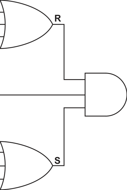
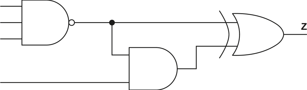
The diagram shows a logic circuit.
A
Show mark scheme
6(a) [3 marks]
mark for working, all five columns P, Q, R, S and T mark for first four rows of column Z mark for second four rows of column Z Working space
6(b) [2 marks]
marks for all six correct terms only mark for any three correct terms (Z = ) A.B.C + A.B.C + A.B.C + A.B.C + A.B.C + A.B.C
6(c)(i) [2 marks]
marks if all correct mark if only one error present 00 01 11 10 0 1 0 1 1 1 1 0 1 1
6(c)(ii) [2 marks]
mark for each correct loop (Max 2) 00 01 11 10 0 1 0 1 1 1 1 0 1 1
B
C

Z
| P | P | P | P | |
| P | P | P | P | |
| P | P | P | P | P |
| P | P | P | P | |
(a) Complete the truth table for the given logic circuit.
Show your working.
| Working space | |||||||
|---|---|---|---|---|---|---|---|
| A | B | C | P | Q | R | S | Z |
| 0 | 0 | 0 | |||||
| 0 | 0 | 1 | |||||
| 0 | 1 | 0 | |||||
| 0 | 1 | 1 | |||||
| 1 | 0 | 0 | |||||
| 1 | 0 | 1 | |||||
| 1 | 1 | 0 | |||||
| 1 | 1 | 1 |
(b) Write the Boolean expression that corresponds to the logic circuit as a sum-of-products. 3 marks 2 marks
Z =
Show mark scheme
6(a) [3 marks]
mark for working, all four columns P, Q, R and S mark for first four rows of column Z mark for second four rows of column Z Working space
6(b) [2 marks]
marks for all five correct terms and no extras mark for any three correct terms (Z =) A.B.C + A.B.C + A.B.C + A.B.C + A.B.C
6(c)(i) [2 marks]
marks if all correct mark if one error present 00 01 11 10 BC
6(c)(ii) [2 marks]
mark for each correct loop (Max 2) 00 01 11 10 BC
Show mark scheme
5 [4 marks]
One mark per mark point – SISD ( Max 2 ) MP1 Single Instruction, Single Data (architecture). // Data is taken from a single source and a single instruction is performed on the data. MP2 Contains one processor, a control unit and a memory unit. MP3 …that executes instructions sequentially. One mark per mark point – MIMD ( Max 2 ) MP4 Multiple Instruction, Multiple Data (architecture). // At any time, any processor can execute different instructions on different sets of data. MP5 Contains many processors MP6 …that operate asynchronously / independently .
This diagram represents a logic circuit.
A
B
C
D
(a) Complete the truth table for the given logic circuit. 3 marks
| A | B | C | D | Working space | Z |
|---|---|---|---|---|---|
| 0 | 0 | 0 | 0 | ||
| 0 | 0 | 0 | 1 | ||
| 0 | 0 | 1 | 0 | ||
| 0 | 0 | 1 | 1 | ||
| 0 | 1 | 0 | 0 | ||
| 0 | 1 | 0 | 1 | ||
| 0 | 1 | 1 | 0 | ||
| 0 | 1 | 1 | 1 | ||
| 1 | 0 | 0 | 0 | ||
| 1 | 0 | 0 | 1 | ||
| 1 | 0 | 1 | 0 | ||
| 1 | 0 | 1 | 1 | ||
| 1 | 1 | 0 | 0 | ||
| 1 | 1 | 0 | 1 | ||
| 1 | 1 | 1 | 0 | ||
| 1 | 1 | 1 | 1 |
Show mark scheme
6(a) [3 marks]
One mark for every shaded block of rows for column Z correct ( Max 3 ) 0 0 0 0 1 0 0 0 1 0 0 0 1 0 1 0 0 1 1 0 0 1 0 0 1 0 1 0 1 0 0 1 1 0 1 0 1 1 1 0 1 0 0 0 1 1 0 0 1 0 1 0 1 0 1 1 0 1 1 0 1 1 0 0 1 1 1 0 1 0 1 1 1 0 0 1 1 1 1 0
6(b) [3 marks]
One mark for correct working from points (Max 2) , for example: (Y =) A.B.C.D + A.B.C.D + A.B.C.D + A.B.C.D (Y =) A.D.(B.C + B.C + B.C + B.C) (Y =) A.D.(B.(C + C) + B.(C + C)) (Y =) A.D.(B.(1) + B.(1)) (Y =) A.D.(B + B) (Y =) A.D.(1) One mark for correct answer (Y =) A.D
Show mark scheme
5(a) [2 marks]
One mark per mark point ( Max 2 ) MP1 Virtual memory is used when RAM is running low MP2 …such as when a computer is running many processes at once. MP3 Virtual memory may be used for efficient use of RAM / the processor MP4 …such as if data / programs are not immediately needed, they can be moved from RAM to virtual memory
5(b) [3 marks]
One mark per mark point ( Max 3 ) MP1 Disk thrashing is a problem that may occur when frequent transfers between main memory and secondary memory take place // Disk thrashing is a problem that may occur when virtual memory is being used MP2 As main memory fills up, more pages need to be swapped in and out of secondary/virtual memory MP3 This swapping leads to a very high rate of hard disk head movements MP4 Eventually, more time is spent swapping the pages/data than processing the data.
Show mark scheme
6(a) [4 marks]
One mark per ring ( Max 4 ). 5 3 2 10 10 2 20 20 60 60 30 30 30 30 60 OR 20 3 60 2 30 10 5 2 60 20 60 30 10 30 30
6(b) [3 marks]
One mark per mark point ( Max 3 ) MP1 The (RPN) expression is read from left to right, one item at a time MP2 Each element is checked to see if it as operator or a value MP3 Values are pushed onto a stack until an operator is found MP4 The operator is applied to the last two values on the stack and the result is pushed back onto the stack MP5 This repeats until a single value remains, which is the solution.
Show mark scheme
5 [4 marks]
One mark per mark point – SISD ( Max 2 ) MP1 Single Instruction, Single Data (architecture). // Data is taken from a single source and a single instruction is performed on the data. MP2 Contains one processor, a control unit and a memory unit. MP3 …that executes instructions sequentially. One mark per mark point – MIMD ( Max 2 ) MP4 Multiple Instruction, Multiple Data (architecture). // At any time, any processor can execute different instructions on different sets of data. MP5 Contains many processors MP6 …that operate asynchronously / independently .
This diagram represents a logic circuit.
A
B
C
D
(a) Complete the truth table for the given logic circuit. 3 marks

| A | B | C | D | Working space | Z |
|---|---|---|---|---|---|
| 0 | 0 | 0 | 0 | ||
| 0 | 0 | 0 | 1 | ||
| 0 | 0 | 1 | 0 | ||
| 0 | 0 | 1 | 1 | ||
| 0 | 1 | 0 | 0 | ||
| 0 | 1 | 0 | 1 | ||
| 0 | 1 | 1 | 0 | ||
| 0 | 1 | 1 | 1 | ||
| 1 | 0 | 0 | 0 | ||
| 1 | 0 | 0 | 1 | ||
| 1 | 0 | 1 | 0 | ||
| 1 | 0 | 1 | 1 | ||
| 1 | 1 | 0 | 0 | ||
| 1 | 1 | 0 | 1 | ||
| 1 | 1 | 1 | 0 | ||
| 1 | 1 | 1 | 1 |
Show mark scheme
6(a) [3 marks]
One mark for every shaded block of rows for column Z correct ( Max 3 ) 0 0 0 0 1 0 0 0 1 0 0 0 1 0 1 0 0 1 1 0 0 1 0 0 1 0 1 0 1 0 0 1 1 0 1 0 1 1 1 0 1 0 0 0 1 1 0 0 1 0 1 0 1 0 1 1 0 1 1 0 1 1 0 0 1 1 1 0 1 0 1 1 1 0 0 1 1 1 1 0
6(b) [3 marks]
One mark for correct working from points (Max 2) , for example: (Y =) A.B.C.D + A.B.C.D + A.B.C.D + A.B.C.D (Y =) A.D.(B.C + B.C + B.C + B.C) (Y =) A.D.(B.(C + C) + B.(C + C)) (Y =) A.D.(B.(1) + B.(1)) (Y =) A.D.(B + B) (Y =) A.D.(1) One mark for correct answer (Y =) A.D
(a) Complete the Karnaugh map (K-map) for the following Boolean expression. 2 marks
Z = A.B.C.D + A.B.C.D + A.B.C.D + A.B.C.D + A.B.C.D + A.B.C.D
| D 00 01 11 10 00 01 11 10 |
||||
|---|---|---|---|---|
| 00 D 00 01 11 10 01 11 10 |
||||
| 00 D 00 01 11 10 01 11 10 |
||||
| 00 D 00 01 11 10 01 11 10 |
||||
| 00 D 00 01 11 10 01 11 10 |
(b) Draw loop(s) around appropriate group(s) in the K-map to produce an optimal sum-of-products. [2]
(c) Write the Boolean logic expression from your answer to part (b) as a simplified sum-of-products. 2 marks
Z =
(d) Use Boolean algebra to give your answer to part (c) in its simplest form.
Z = [1]
Show mark scheme
7(a)
Two marks if no errors present One mark if one error present
7(b) [2 marks]
One mark for each correct loop (Max 2)
7(c) [2 marks]
One mark for each mark point ( Max 2 ) Any correct Boolean term Boolean terms and operator correct and no other terms present (Z =) AC + BC
7(d) [3 marks]
One mark for simplest form ( Max 1 ) (Z =) C (A + B)
Show mark scheme
9(a)
One mark for every two correct products ( Max 3 ) (Z =) ABCD + ABCD + ABCD + ABCD + ABCD + ABCD
9(b) [2 marks]
Two marks if no errors present One mark if one error present
9(c) [2 marks]
One mark for each correct loop (Max 2)
9(d) [2 marks]
One mark for each mark point ( Max 2 ) Any correct Boolean term Boolean terms and operator correct and no other terms present (Z =) AB + AC
9(e) [1 mark]
One mark for simplest form ( Max 1 ) (Z =) A (B + C)
| epresents a logic circuit. | ||||
|---|---|---|---|---|
| INPUT | INPUT | INPUT | INPUT | OUTPUT |
| A | B | C | D | Z |
| 0 | 0 | 0 | 0 | 1 |
| 0 | 0 | 0 | 1 | 1 |
| 0 | 0 | 1 | 0 | 1 |
| 0 | 0 | 1 | 1 | 1 |
| 0 | 1 | 0 | 0 | 0 |
| 0 | 1 | 0 | 1 | 0 |
| 0 | 1 | 1 | 0 | 1 |
| 0 | 1 | 1 | 1 | 1 |
| 1 | 0 | 0 | 0 | 0 |
| 1 | 0 | 0 | 1 | 0 |
| 1 | 0 | 1 | 0 | 0 |
| 1 | 0 | 1 | 1 | 0 |
| 1 | 1 | 0 | 0 | 0 |
| 1 | 1 | 0 | 1 | 0 |
| 1 | 1 | 1 | 0 | 0 |
| 1 | 1 | 1 | 1 | 0 |
(a) Write the Boolean logic expression that corresponds to the given truth table as the sum‑of‑products. 3 marks
Z =
Show mark scheme
10(a)
One mark from: Supervised (learning) Unsupervised (learning) Reinforcement (learning) Deep (learning)
10(b) [5 marks]
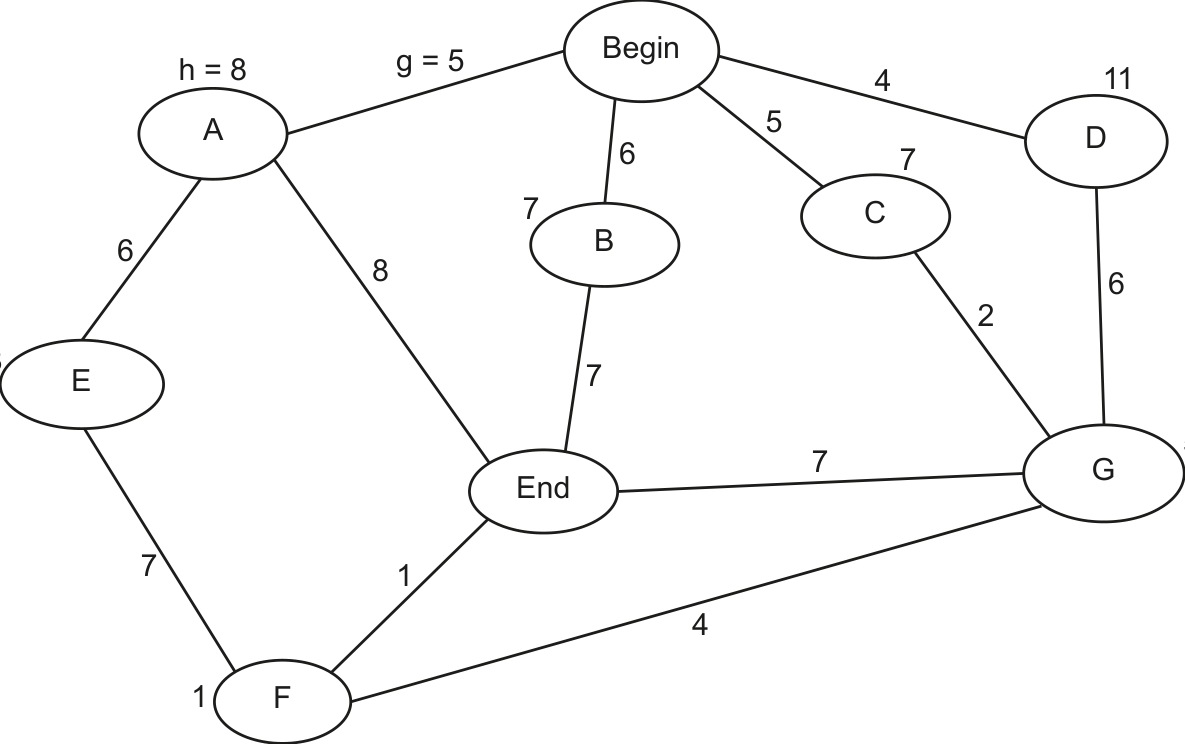
One mark for each correct calculation as follows (Max 2) : Node B (from Begin) (Line 3 in table) Node C (from Begin) (Line 4 in table) Node D (from Begin) (Line 5 in table) One mark for each correct calculation as follows (Max 2) : Node G (from C) (Line 6 in table) Node F and Node End (from G) (Lines 7 and 8 in table) Node End (from F) (Line 9 in table) One mark for correct path (Max 1) : Begin End Cost from Heuristic Total Start Destination start node (h) (f = g + h) node node (g) Begin Begin 0 12 12 Begin A 5 8 13 Begin B 6 7 13 Begin C 5 7 12 Begin D 4 11 15 5 + 2 = 7 5 12 5 + 2 + 4 = 11 1 12 G End 5 + 2 + 7 = 14 0 14 5 + 2 + 4 + 1 = F End 0 12 12 Final Path Begin End
(b) Complete the Karnaugh map (K‑map) for the given truth table. 2 marks
AB
CD
(c) Draw loop(s) around appropriate group(s) in the K‑map to produce an optimal sum‑of‑products. 2 marks
(d) Write the Boolean logic expression from your answer to part (c) as a simplified sum‑of‑products. 2 marks
Z =
(e) Use Boolean algebra to give your answer to part (d) in its simplest form. 1 mark
Z = [1]
10 (a) State one category of machine learning.
(b) Calculate the path that takes the shortest time to travel from the Begin node to the End node, using the A* algorithm. 5 marks 2 marks
Show your working in the table provided.
The first two rows have already been completed.
| Start node | Destination node |
Cost from start node (g) |
Heuristic (h) |
Total (f = g + h) |
|---|---|---|---|---|
| Begin | Begin | 0 | 12 | 12 |
| Begin | A | 5 | 8 | 13 |
Final path 11 (a) The pseudocode shown represents a queue Abstract Data Type (ADT) with procedures for initialisation and to add new items. It is incomplete.
    CONSTANT MaxLength = 50
    DECLARE FrontPointer : INTEGER
    DECLARE RearPointer : INTEGER
    DECLARE Length : INTEGER
    DECLARE Queue : ARRAY[0 : MaxLength – 1] OF STRING
    // initialisation of queue
    PROCEDURE Initialise
    FrontPointer  ‑1
______ 0
    ENDPROCEDURE
    // adding a new item to the queue
    PROCEDURE Enqueue(NewItem : STRING)
IF ______ THEN
RearPointer
    IF RearPointer > MaxLength – 1 THEN
    RearPointer  0
    ENDIF
    Length  Length + 1
    ENDIF
    ENDPROCEDURE
| (i) Study the pseudoc | code and insert th | he identifiers to complete this table. |
|---|---|---|
| Identifier | Data type | Description |
STRING |
An array to store the contents of the queue. | |
INTEGER |
Points to the last item of the queue. | |
INTEGER |
Indicates the number of items in the queue. | |
INTEGER |
Points to the first item of the queue. |
(ii) Complete the given pseudocode. [5]
(b) Explain the reasons why a queue ADT works better than a stack ADT in organising print jobs. 3 marks
Show mark scheme
11(a)(i) [5 marks]
One mark for every two correct identifiers (Max 2) Identifier Data type Description Queue STRING An array to store the contents of the queue. RearPointer INTEGER Points to the last term of the queue. Length INTEGER Indicates the number of items in the queue. FrontPointer INTEGER Points to the first term of the queue.
11(a)(ii)
One mark for each correctly completed line ( Max 5 ) CONSTANT MaxLength = 50 DECLARE FrontPointer : INTEGER DECLARE RearPointer : INTEGER DECLARE Length : INTEGER DECLARE Queue : ARRAY[0:MaxLength – 1] OF STRING // Initialisation of queue PROCEDURE Initialise FrontPointer -1 RearPointer -1 Length 0 ENDPROCEDURE // Adding a new item to the queue PROCEDURE Enqueue(NewItem : STRING) IF Length < MaxLength THEN // IF Length <= MaxLength - 1 THEN RearPointer RearPointer + 1 IF RearPointer > MaxLength – 1 THEN RearPointer 0 ENDIF Queue[RearPointer] NewItem Length Length + 1 ENDIF ENDPROCEDURE
11(b) [3 marks]
One mark per mark point ( Max 3 ) Print jobs are expected to be actioned by the printer in the order they are received … because the printer queue is a queue, the first job to be sent to the printer would be the first job printed. If the printer queue was on a stack, the first job the printer received would not be printed until all the other jobs have been printed.
(a) Complete the Karnaugh map (K-map) for the following Boolean expression. 2 marks
Z = A.B.C.D + A.B.C.D + A.B.C.D + A.B.C.D + A.B.C.D + A.B.C.D
| D 00 01 11 10 00 01 11 10 |
||||
|---|---|---|---|---|
| 00 D 00 01 11 10 01 11 10 |
||||
| 00 D 00 01 11 10 01 11 10 |
||||
| 00 D 00 01 11 10 01 11 10 |
||||
| 00 D 00 01 11 10 01 11 10 |
(b) Draw loop(s) around appropriate group(s) in the K-map to produce an optimal sum-of-products. [2]
(c) Write the Boolean logic expression from your answer to part (b) as a simplified sum-of-products. 2 marks
Z =
(d) Use Boolean algebra to give your answer to part (c) in its simplest form.
Z = [1]
Show mark scheme
7(a)
Two marks if no errors present One mark if one error present
7(b) [2 marks]
One mark for each correct loop (Max 2)
7(c) [2 marks]
One mark for each mark point ( Max 2 ) Any correct Boolean term Boolean terms and operator correct and no other terms present (Z =) AC + BC
7(d) [3 marks]
One mark for simplest form ( Max 1 ) (Z =) C (A + B)
A message is encrypted using a private key and sent to an individual using asymmetric encryption.
(a) State what is meant by a private key . 2 marks
(b) Describe the process of asymmetric encryption. 2 marks
Show mark scheme
6(a) [2 marks]
One mark for each correct point ( Max 2 ) • A private key is the unpublished/secret key/never transmitted anywhere. • It has a matching public key • It is used to decrypt data that was encrypted with its matching public key.
6(b) [2 marks]
One mark for each correct point ( Max 2 ) • The message to be sent is encrypted using the recipient’s public key. // The message to be sent is encrypted using the sender’s private key. • The message is decrypted using the recipient’s private key. // The message is decrypted using the key.
6(c) [4 marks]
One mark for each correct point ( Max 4 ) • The message together with the digital signature is decrypted using the receiver’s private key • The digital signature received is decrypted with the sender’s public key to recover the message digest sent • The decrypted message received is hashed with the agreed hashing algorithm to reproduce the message digest of the message received • The two message digests are compared • … if both digests are the same the message has not been altered // if they are different the message has been altered.
(a) State two differences between symmetric and asymmetric encryption. 2 marks
(b) Explain the process by which an organisation may acquire its digital certificate. 4 marks
Show mark scheme
6(a) [2 marks]
One mark for each point • Symmetric encryption uses a single key and asymmetric encryption uses a pair of keys. • The symmetric single key is used by all, whereas only one of the keys for asymmetric encryption is available to everyone / one of the asymmetric encryption keys needs to be kept secret.
6(b) [4 marks]
One mark for each point ( Max 4 ) • The organisation requests a certificate from a Certificate Authority (CA) • The organisation may send their public key to CA • The organisation gathers all the information required by the CA in order to obtain their certificate, which includes information to prove their identity • The CA verifies the organisation’s identity • The CA generates / issues the certificate including the organisation’s public key (and other information).
A message is encrypted using a private key and sent to an individual using asymmetric encryption.
(a) State what is meant by a private key . 2 marks
(b) Describe the process of asymmetric encryption. 2 marks
Show mark scheme
6(a) [2 marks]
One mark for each correct point ( Max 2 ) • A private key is the unpublished/secret key/never transmitted anywhere. • It has a matching public key • It is used to decrypt data that was encrypted with its matching public key.
6(b) [2 marks]
One mark for each correct point ( Max 2 ) • The message to be sent is encrypted using the recipient’s public key. // The message to be sent is encrypted using the sender’s private key. • The message is decrypted using the recipient’s private key. // The message is decrypted using the key.
6(c) [4 marks]
One mark for each correct point ( Max 4 ) • The message together with the digital signature is decrypted using the receiver’s private key • The digital signature received is decrypted with the sender’s public key to recover the message digest sent • The decrypted message received is hashed with the agreed hashing algorithm to reproduce the message digest of the message received • The two message digests are compared • … if both digests are the same the message has not been altered // if they are different the message has been altered.
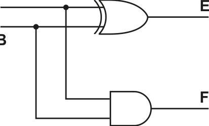
A logic circuit has two inputs A and B, and two outputs E and F .
(a) Complete the truth table for this logic circuit. 2 marks
| INPUT | OUTPUT | ||
|---|---|---|---|
| A | B | E | F |
| 0 | 0 | ||
| 0 | 1 | ||
| 1 | 0 | ||
| 1 | 1 |
(b) (i) State the name of this logic circuit. 1 mark
(ii) State the purpose of each output E and F . 2 marks
Purpose of E
Purpose of F
Show mark scheme
6(a) [2 marks]
1 mark per correct output column INPUT OUTPUT
6(b)(i) [1 mark]
Half adder
6(b)(ii) [2 marks]
Purpose of E: Sum Purpose of F: Carry
(a) Write the Boolean expression that corresponds to the given truth table as a sum-of-products. 3 marks
| INPUT | OUTPUT | |||
|---|---|---|---|---|
| A | B | C | D | Z |
| 0 | 0 | 0 | 0 | 0 |
| 0 | 0 | 0 | 1 | 0 |
| 0 | 0 | 1 | 0 | 0 |
| 0 | 0 | 1 | 1 | 0 |
| 0 | 1 | 0 | 0 | 0 |
| 0 | 1 | 0 | 1 | 0 |
| 0 | 1 | 1 | 0 | 0 |
| 0 | 1 | 1 | 1 | 0 |
| 1 | 0 | 0 | 0 | 0 |
| 1 | 0 | 0 | 1 | 1 |
| 1 | 0 | 1 | 0 | 0 |
| 1 | 0 | 1 | 1 | 1 |
| 1 | 1 | 0 | 0 | 1 |
| 1 | 1 | 0 | 1 | 1 |
| 1 | 1 | 1 | 0 | 1 |
| 1 | 1 | 1 | 1 | 1 |
Z =
Show mark scheme
7(a)
One mark per two correct products (Max 3) _ _ _
( Z =) + + + + _ +
7(b)(i) [2 marks]
One mark for every two correct rows or columns (Max 2) AB 00 01 11 10 00 0 0 1 0 01 0 0 1 1 CD 11 0 0 1 1 10 0 0 1 0
7(b)(ii)
One mark for correct loop (Max 2) AB 00 01 11 10 0 1 00 0 0 01 0 0 1 1 CD 11 0 0 1 1 01 0 0 1 0
7(b)(iii) [2 marks]
One mark per correct marking point (Max 2) // • + // + • ( Z =) + // +
7(b)(iv) [1 mark]
( Z =) A ( B + D ) // A ( D + B )
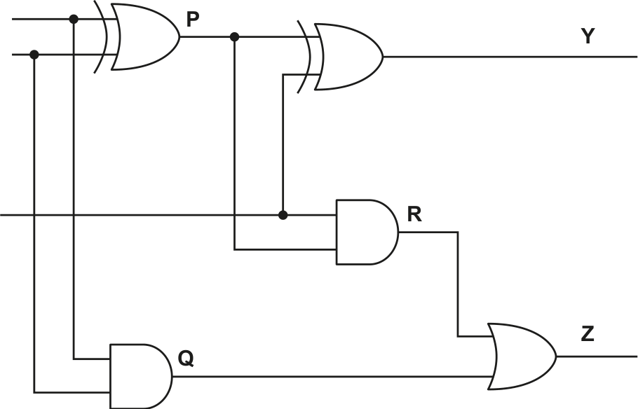
The diagram shows a logic circuit.
A
B
C

(a) Complete the truth table for the given logic circuit. Show your working. 3 marks
| Inputs | Working space | Outputs | |||||
|---|---|---|---|---|---|---|---|
| A | B | C | P | Q | R | Y | Z |
| 0 | 0 | 0 | |||||
| 0 | 0 | 1 | |||||
| 0 | 1 | 0 | |||||
| 0 | 1 | 1 | |||||
| 1 | 0 | 0 | |||||
| 1 | 0 | 1 | |||||
| 1 | 1 | 0 | |||||
| 1 | 1 | 1 |
(b) State the name of the logic circuit. 1 mark
(c) Write the Boolean expressions for the two outputs Y and Z in the truth table as sum-of-products and state the purpose of each output. 4 marks
Y =
Purpose
Z =
Purpose
Show mark scheme
7(a) [3 marks]
One mark for working, (all three columns P, Q and R) One mark for each correct column Y, Z 0 0 0 0 0 0 0 0 0 0 1 0 0 0 1 0 0 1 0 1 0 0 1 0 0 1 1 1 0 1 0 1 1 0 0 1 0 0 1 0 1 0 1 1 0 1 0 1 1 1 0 0 1 0 0 1 1 1 1 0 1 0 1 1
7(b) [4 marks]
Full adder
7(c)
One mark for each point
Y = A B C + A B C + A B C + A B C Purpose: Sum bit
Z = A B C + A B C + A B C + A B C Purpose: Carry output
The diagram shows a logic circuit.
A
B
C
(a) Complete the truth table for the given logic circuit. Show your working. 3 marks
| Inputs | Working space | Outputs | |||||
|---|---|---|---|---|---|---|---|
| A | B | C | P | Q | R | Y | Z |
| 0 | 0 | 0 | |||||
| 0 | 0 | 1 | |||||
| 0 | 1 | 0 | |||||
| 0 | 1 | 1 | |||||
| 1 | 0 | 0 | |||||
| 1 | 0 | 1 | |||||
| 1 | 1 | 0 | |||||
| 1 | 1 | 1 |
(b) State the name of the logic circuit. 1 mark
(c) Write the Boolean expressions for the two outputs Y and Z in the truth table as sum-of-products and state the purpose of each output. 4 marks
Y =
Purpose
Z =
Purpose
Show mark scheme
7(a) [3 marks]
One mark for working, (all three columns P, Q and R) One mark for each correct column Y, Z 0 0 0 0 0 0 0 0 0 0 1 0 0 0 1 0 0 1 0 1 0 0 1 0 0 1 1 1 0 1 0 1 1 0 0 1 0 0 1 0 1 0 1 1 0 1 0 1 1 1 0 0 1 0 0 1 1 1 1 0 1 0 1 1
7(b) [4 marks]
Full adder
7(c)
One mark for each point
Y = A B C + A B C + A B C + A B C Purpose: Sum bit
Z = A B C + A B C + A B C + A B C Purpose: Carry output