4.2 Assembly Language
AS Level · 25 questions found
What this topic covers
Section titled “What this topic covers”- Relationship between assembly language and machine code
- Two-pass assembler: stages and applying to a program
- Trace a simple assembly language program
- Instruction groups: data movement, I/O, arithmetic, jump, compare
- Addressing modes: immediate, direct, indirect, indexed, relative
- Key instructions: LDM, LDD, LDI, LDX, STO, ADD, SUB, JMP, CMP, JPE, JPN, IN, OUT, END
Past paper questions
Section titled “Past paper questions”The table shows part of the instruction set for a processor. The processor has one register, the Accumulator (ACC).
| Instruction | Explanation | |
|---|---|---|
| Opcode | Operand | Operand |
| AND | #n / Bn / &n | Bitwise AND operation of the contents of the ACC with the operand |
| AND | Bitwise AND operation of the contents of the ACC with the contents of |
|
| XOR | #n / Bn / &n | Bitwise XOR operation of the contents of the ACC with the operand |
| XOR | Bitwise XOR operation of the contents of the ACC with the contents of |
|
| OR | #n / Bn / &n | Bitwise OR operation of the contents of the ACC with the operand |
| OR | Bitwise OR operation of the contents of the ACC with the contents of |
|
| LSL | #n | Bits in ACC are shifted logically n places to the left. Zeros are introduced on the right-hand end. |
| LSR | #n | Bits in ACC are shifted logically n places to the right. Zeros are introduced on the left-hand end. |
| can be an absolute or symbolic address # denotes a denary number, e.g. #127 B denotes a binary number, e.g. B10010001 & denotes a hexadecimal number, e.g. &4A |
can be an absolute or symbolic address # denotes a denary number, e.g. #127 B denotes a binary number, e.g. B10010001 & denotes a hexadecimal number, e.g. &4A |
can be an absolute or symbolic address # denotes a denary number, e.g. #127 B denotes a binary number, e.g. B10010001 & denotes a hexadecimal number, e.g. &4A |
(a) The ACC currently contains the following positive binary integer:
0 0 0 1 1 1 1 0
Write a bit manipulation instruction that uses a binary shift to change the contents of the ACC to:
0 1 1 1 1 0 0 0
Instruction [1]
(b) The ACC currently contains the following positive binary integer: 1 mark
1 1 1 0 0 0 1 1
Write the contents of the ACC after the instruction XOR &12 is carried out.
(c) The ACC currently contains the following positive binary integer: 1 mark
1 1 1 0 0 0 1 1
Write the contents of the ACC after the instruction AND #63 is carried out.
(d) The ACC currently contains the following positive binary integer: 1 mark
1 1 1 0 0 0 1 1
The current contents of memory are:
Address Data
98 00100100
99 00110001
100 00110011
101 10100011
102 10101100
Write the contents of the ACC after the instruction OR 100 is carried out.
Show mark scheme
4(a) [1 mark]
1 mark for: LSL #2
4(b) [1 mark]
1 1 1 1 0 0 0 1
4(c) [1 mark]
0 0 1 0 0 0 1 1
4(d) [1 mark]
1 1 1 1 0 0 1 1
(a) (i) State what is meant by relative addressing. 1 mark
(ii) Registers such as the Accumulator (ACC) and the Index Register (IX) are used in the CPU. 2 marks
Identify two special purpose registers used in the CPU. Do not include the ACC or IX in your answers.
1
2
(b) The following table shows part of the instruction set for a processor. The processor has two registers: the ACC and an IX. 3 marks
| Instruction | Explanation | |
|---|---|---|
| Opcode | Operand | Operand |
| LDM | #n | Immediate addressing. Load the number n to ACC |
| LDD | Direct addressing. Load the contents of the location at the given address to ACC |
|
| LDI | Indirect addressing. The address to be used is at the given address. Load the contents of this second address to ACC |
|
| LDX | Indexed addressing. Form the address from + the contents of the index register. Copy the contents of this calculated address to ACC |
|
| LDR | #n | Immediate addressing. Load the number n to IX |
| can be an absolute or symbolic address # denotes a denary number, e.g. #127 |
can be an absolute or symbolic address # denotes a denary number, e.g. #127 |
can be an absolute or symbolic address # denotes a denary number, e.g. #127 |
The current contents of the main memory and the index register are shown.
Address Instruction
98 8
99 16
100 3
101 98
102 32
IX 2
Write the contents of the ACC after each instruction is executed.
| Instruction | Value in ACC |
|---|---|
| LDM #98 | |
| LDI 101 | |
| LDX 100 |
(c) A student buys a new computer. The table shows the specifications of the old computer and the new computer. 4 marks
| Old computer | New computer |
|---|---|
| 1.8 GHz dual core processor | 2.3 GHz dual core processor |
| 16 MB cache | 32 MB cache |
Explain why increasing the clock speed and increasing the cache memory will improve the performance of the computer.
Clock speed
Cache memory
Show mark scheme
3(a)(i) [1 mark]
1 mark • The value of the operand is an offset value which is added to another base value to give the address from which the contents are loaded to the accumulator
3(a)(ii) [2 marks]
1 mark per bullet point, max 2 marks • Program counter (PC) • Memory Data Register (MDR) • Memory Address Register (MAR) • Current Instruction Register (CIR) • Status Register
3(b) [3 marks]
1 mark for each correct value, max 3 marks Instruction Value in ACC LDM #98 98 LDI 101 8 LDX 100 32
3(c) [4 marks]
1 mark per bullet point, max 2 marks for each Clock Speed: • Processor can perform more F-E cycles per second • ... so more instructions / data can be processed each second Cache Memory: • Can store more of the most frequently used instructions • … which reduces the need to access slower RAM
The following table shows part of the instruction set for a processor. The processor has two registers: the Accumulator (ACC) and the Index Register (IX).
| Instruction | Explanation | |
|---|---|---|
| Opcode | Operand | Operand |
| LDM | #n | Immediate addressing. Load the number n to the ACC |
| AND | #n / Bn / &n | Bitwise AND operation of the contents of the ACC with the operand |
| AND | Bitwise AND operation of the contents of the ACC with the contents of |
|
| XOR | #n / Bn / &n | Bitwise XOR operation of the contents of the ACC with the operand |
| XOR | Bitwise XOR operation of the contents of the ACC with the contents of |
|
| OR | #n / Bn / &n | Bitwise OR operation of the contents of the ACC with the operand |
| OR | Bitwise OR operation of the contents of the ACC with the contents of |
|
| CMP | #n | Compare the contents of the ACC with number n |
| CMP | Compare the contents of the ACC with the contents of | |
| LSL | #n | Bits in the ACC are shifted logically n places to the left. Zeros are introduced on the right‑hand end |
| LSR | #n | Bits in the ACC are shifted logically n places to the right. Zeros are introduced on the left‑hand end |
| can be an absolute or symbolic address # denotes a denary number, e.g. #127 B denotes a binary number, e.g. B10010001 & denotes a hexadecimal number, e.g. &4A |
can be an absolute or symbolic address # denotes a denary number, e.g. #127 B denotes a binary number, e.g. B10010001 & denotes a hexadecimal number, e.g. &4A |
can be an absolute or symbolic address # denotes a denary number, e.g. #127 B denotes a binary number, e.g. B10010001 & denotes a hexadecimal number, e.g. &4A |
The current contents of main memory are shown:
Address Data
100 0000 0011
101 1010 1110
102 1100 1100
103 1111 1111
104 1100 1100
(a) Complete the table by writing the contents of the ACC after the execution of each instruction. 4 marks
| Current contents of the ACC |
Instruction | Contents of the ACC after the execution of the instruction |
|---|---|---|
| 0000 1111 | AND 101 | |
| 0000 0000 | LDM #100 | |
| 0000 0001 | XOR &F1 | |
| 0001 0001 | CMP 101 |
(b) The Von Neumann model for a computer system uses registers. 4 marks
Describe the role of the Memory Address Register (MAR) and Memory Data Register (MDR) in the fetch‑execute (F‑E) cycle.
(c) Assembly language instructions are grouped. 3 marks
Complete each statement by writing the name of the appropriate instruction group.
Loading data into the accumulator is an example of an instruction in the
______ group. Incrementing the index register is an example
of an instruction in the ______ group. Branching to another
address is an example of an instruction in the ______ group.
Show mark scheme
6(a) [4 marks]
1 mark for each correct row Current contents Instruction Contents of the ACC of the ACC after the execution of the instruction 0000 1111 AND 101 0000 1110 0000 0000 LDM #100 0110 0100 0000 0001 XOR &F1 1111 0000 0001 0001 CMP 101 0001 0001
6(b) [4 marks]
1 mark for each bullet point, max 4 marks • MAR stores the address of the next instruction / data to be read from / or written to memory • The address is received from the Program Counter (PC) • The MDR stores the data / instruction in the address stored in the MAR which has been read / written • The instruction passes to the CIR for decoding and executing
6(c) [3 marks]
1 mark for each bullet point, max 3 marks • Data movement • Arithmetic operations • Conditional and unconditional (jump) instructions
The table shows assembly language instructions for a processor that has one register, the Accumulator (ACC).
| Label | Instruction | Explanation | |
|---|---|---|---|
| Label | Opcode | Operand | Operand |
| LDM | #n | Load the number n to ACC | |
| LDD | Load the contents of the location at the given address to the ACC |
||
| LDI | The address to be used is at the given address. Load the contents of this second address to the ACC |
||
| ADD | Add the contents of the given address to the ACC |
||
| SUB | Subtract the contents of the given address from the ACC |
||
| STO | Store the contents of the ACC at the given address |
||
| Gives a symbolic address | |||
| # denotes a denary number, e.g. #123 |
# denotes a denary number, e.g. #123 |
# denotes a denary number, e.g. #123 |
# denotes a denary number, e.g. #123 |
(a) Write assembly language code, using only the given instruction set to: 6 marks
store the denary value 100 as a named constant
subtract the constant from the value contained in address 632
store the result in variable Answer.
Show the initialisation of the constant and Answer in the table provided.
| Label | Contents |
|---|---|
(b) The address 632 contains the value 45. 1 mark
State the value of Answer after the code described in part (a) has executed.
Show mark scheme
11(a) [6 marks]
One mark per mark point ( Max 6 ) MP1 seen LDM #100 MP2 Correct use of with labelled address (constant or answer) STO MP3 Correct use of LDD 632 MP4 Correct use of with labelled address (constant) SUB Opcode Operand LDM #100 STO Constant LDD 632 SUB Constant STO Answer MP5 Storing at a labelled address away from the code 100 MP6 Labelling both addresses away from the code. Label Contents Constant: 100 Answer:
11(b) [1 mark]
–55
The table shows assembly language instructions for a processor that has one register, the Accumulator (ACC).
| Label | Instruction | Explanation | |
|---|---|---|---|
| Label | Opcode | Operand | Operand |
| LDM | #n | Load the number n to the ACC | |
| LDD | Load the contents of the location at the given address to ACC |
||
| LDI | The address to be used is at the given address. Load the contents of this second address to the ACC. |
||
| ADD | Add the contents of the given address to the ACC |
||
| SUB | Subtract the contents of the given address from the ACC |
||
| STO | Store the contents of the ACC at the given address |
||
| Gives a symbolic address | |||
| # denotes a denary number, e.g. #123 |
# denotes a denary number, e.g. #123 |
# denotes a denary number, e.g. #123 |
# denotes a denary number, e.g. #123 |
The current contents of memory are:
| Address | Contents |
|---|---|
| 150 | 26 |
| 300 | 86 |
| 420 | 150 |
Write assembly language code, using only the given instruction set to:
store the contents of location 300 as labelled variable A
store the contents of location 420 as labelled variable B
add the value stored in the address contained in variable B to the value contained in variable A
store the result in variable Answer.
Show the initialisation and values of the variables A, B and Answer in the table provided. 7 marks
| Label | Content |
|---|---|
Show mark scheme
11 [7 marks]
One mark per mark point ( Max 7 ) MP1 seen LDD 300 MP2 Correct use of seen (at least once) STO MP3 Correct use of seen LDD 420 MP4 Correct use of LDI B MP5 Correct use of ADD A Opcode Operand LDD 300 STO A LDD 420 STO B LDI B ADD A STO Answer MP6 Correct labelling of three addresses , and A: B: Answer: MP7 Correct contents in and A: B: MP8 Correct value in Answer: Label Contents A: 86 B: 150 Answer: 112
The table shows assembly language instructions for a processor that has one register, the Accumulator (ACC).
| Label | Instruction | Explanation | |
|---|---|---|---|
| Label | Opcode | Operand | Operand |
| LDM | #n | Load the number n to the ACC | |
| LDD | Load the contents of the location at the given address to the ACC |
||
| LDI | The address to be used is at the given address. Load the contents of this second address to the ACC |
||
| ADD | Add the contents of the given address to the ACC |
||
| ADD | #n | Add the number n to the ACC | |
| SUB | Subtract the contents of the given address from the ACC |
||
| SUB | #n | Subtract the number n from the ACC | |
| STO | Store the contents of the ACC at the given address |
||
| Gives a symbolic address | |||
| # denotes a denary number, e.g. #123 |
# denotes a denary number, e.g. #123 |
# denotes a denary number, e.g. #123 |
# denotes a denary number, e.g. #123 |
The current contents of memory are:
| Address | Contents |
|---|---|
| 563 | 125 |
| 899 | 63 |
Write assembly language code, using only the given instruction set to:
store the denary value 250 as labelled variable X
store the value stored in location 563 as labelled variable Y
add the value stored in variable X to the value stored in variable Y
subtract the value stored in location 899 from the current value in the Accumulator
store the result in variable Total.
Show the initialisation and values of the variables X, Y and Total in the table provided. 7 marks
| Label | Content |
|---|---|
Show mark scheme
13 MP6 Correct setting up of at least one labelled address and its value MP7 Correct setting up of remaining two labelled addresses and their values Label Contents X: 250 Y: 125 Total: 312
(a) The following table shows part of the instruction set for a processor. The processor has two registers: the Accumulator (ACC) and an Index Register (IX). 4 marks
| Instruction | Explanation | |
|---|---|---|
| Opcode | Operand | Operand |
| LDM | #n | Immediate addressing. Load the number n to ACC |
| LDD | Direct addressing. Load the contents of the location at the given address to ACC |
|
| LDI | Indirect addressing. The address to be used is at the given address. Load the contents of this second address to ACC |
|
| INC | Add 1 to the contents of the register (ACC or IX) | |
| STO | Store the contents of ACC at the given address | |
| ADD | #n/Bn/&n | Add the number n to the ACC |
| DEC | Subtract 1 from the contents of the register (ACC or IX) | |
| JMP | Jump to the given address | |
| CMP | Compare the contents of ACC with the contents of | |
| JPE | Following a compare instruction, jump to if the compare was True |
|
| END | Return control to the operating system | |
| ACC denotes Accumulator can be an absolute or a symbolic address # denotes a denary number, e.g. #123 B denotes a binary number, e.g. B01001010 & denotes a hexadecimal number, e.g. &4A |
ACC denotes Accumulator can be an absolute or a symbolic address # denotes a denary number, e.g. #123 B denotes a binary number, e.g. B01001010 & denotes a hexadecimal number, e.g. &4A |
ACC denotes Accumulator can be an absolute or a symbolic address # denotes a denary number, e.g. #123 B denotes a binary number, e.g. B01001010 & denotes a hexadecimal number, e.g. &4A |
The current contents of memory are:
address
...
200
201
202
Instruction
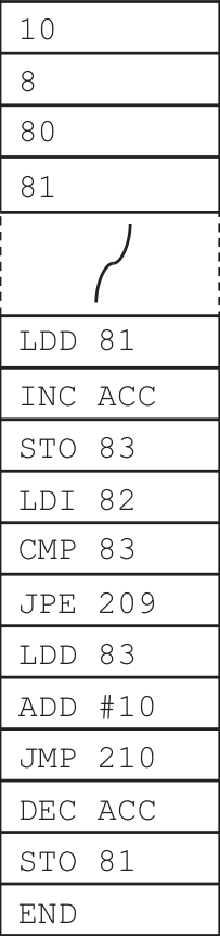
Trace the program currently in memory using the following trace table.
| Instruction address | ACC | Memory address | |||
|---|---|---|---|---|---|
| Instruction address | ACC | 80 | 81 | 82 | 83 |
| 10 | 8 | 80 | 81 | ||
(b) The table shows part of the instruction set for a processor. The processor has one register:
the Accumulator (ACC).
| Instruction | Explanation | |
|---|---|---|
| Opcode | Operand | Operand |
| AND | #n/Bn/&n | Bitwise AND operation of the contents of ACC with the operand |
| AND | Bitwise AND operation of the contents of ACC with the contents of |
|
| XOR | #n/Bn/&n | Bitwise XOR operation of the contents of ACC with the operand |
| XOR | Bitwise XOR operation of the contents of ACC with the contents of |
|
| OR | #n/Bn/&n | Bitwise OR operation of the contents of ACC with the operand |
| OR | Bitwise OR operation of the contents of ACC with the contents of |
|
| LSL | #n | Bits in ACC are shifted logically n places to the left. Zeros are introduced on the right‑hand end |
| LSR | #n | Bits in ACC are shifted logically n places to the right. Zeros are introduced on the left‑hand end |
| can be an absolute or symbolic address # denotes a denary number, e.g. #123 B denotes a binary number, e.g. B01001010 & denotes a hexadecimal number, e.g. &4A |
can be an absolute or symbolic address # denotes a denary number, e.g. #123 B denotes a binary number, e.g. B01001010 & denotes a hexadecimal number, e.g. &4A |
can be an absolute or symbolic address # denotes a denary number, e.g. #123 B denotes a binary number, e.g. B01001010 & denotes a hexadecimal number, e.g. &4A |
(i) Write the bit manipulation instruction that can be used to set the least significant bit to 1 in an 8‑bit register. All other bits must remain unchanged. 1 mark
The instruction needs to work on a register that contains any 8‑bit binary number.
(ii) The ACC currently contains the following binary value. 1 mark
0 1 0 1 0 1 0 1
Write the result after the instruction XOR &FE is run.
(iii) The ACC currently contains the following binary value. 1 mark
0 1 1 0 1 0 1 1
Write the result after the instruction LSR #5 is run.
Show mark scheme
8(a) [4 marks]
1 mark for each shaded section Instruction Memory address address ACC 80 81 82 83 10 8 80 81 200 8 201 9 202 9 203 10 204 206 9 207 19 208 210 19
8(b)(i) [1 mark]
1 mark for: OR B0000 0001 // OR #1 // OR &1
8(b)(ii) [1 mark]
1 mark for: 1010 1011
8(b)(iii) [1 mark]
1 mark for: 0000 0011
(a) The following table shows part of the instruction set for a processor. The processor has one register: the Accumulator (ACC).
| Instruction | Explanation | |
|---|---|---|
| Opcode | Operand | Operand |
| LDD | Direct addressing. Load the contents of the location at the given address to ACC |
|
| LDM | #n | Immediate addressing. Load the number n to ACC |
| STO | Store the contents of ACC at the given address | |
| ADD | #n/Bn/&n | Add the number n to the ACC |
| ADD | Add the contents of the given address to the ACC | |
| INC | Add 1 to the contents of the register (ACC) | |
| CMP | Compare the contents of ACC with the contents of | |
| CMP | #n | Compare the contents of ACC with number n |
| JPE | Following a compare instruction, jump to if the compare was True |
|
| JMP | Jump to the given address | |
| END | Return control to the operating system | |
| ACC denotes Accumulator can be an absolute or a symbolic address # denotes a denary number, e.g. #123 B denotes a binary number, e.g. B01001010 & denotes a hexadecimal number, e.g. &4A |
ACC denotes Accumulator can be an absolute or a symbolic address # denotes a denary number, e.g. #123 B denotes a binary number, e.g. B01001010 & denotes a hexadecimal number, e.g. &4A |
ACC denotes Accumulator can be an absolute or a symbolic address # denotes a denary number, e.g. #123 B denotes a binary number, e.g. B01001010 & denotes a hexadecimal number, e.g. &4A |
The current contents of memory are:
Address Instruction
…
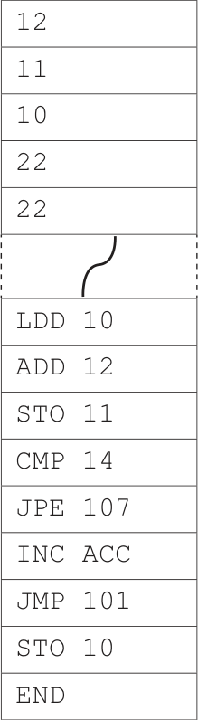
(i) Trace the program currently in memory using the following trace table. 3 marks
| Instruction address | ACC | Memory address | ||||
|---|---|---|---|---|---|---|
| Instruction address | ACC | 10 | 11 | 12 | 13 | 14 |
| 12 | 11 | 10 | 22 | 22 | ||
(ii) State the effect of changing instruction LDD 10 in address 100 to LDM #10 1 mark
(iii) Identify and describe one mode of addressing not given in the table of instructions in part (a). 2 marks
Mode of addressing
Description
(b) The table shows part of the instruction set for a processor. The processor has one register:
the Accumulator (ACC).
| Instruction | Explanation | |
|---|---|---|
| Opcode | Operand | Operand |
| AND | #n/Bn/&n | Bitwise AND operation of the contents of ACC with the operand |
| AND | Bitwise AND operation of the contents of ACC with the contents of |
|
| XOR | #n/Bn/&n | Bitwise XOR operation of the contents of ACC with the operand |
| XOR | Bitwise XOR operation of the contents of ACC with the contents of |
|
| OR | #n/Bn/&n | Bitwise OR operation of the contents of ACC with the operand |
| OR | Bitwise OR operation of the contents of ACC with the contents of |
|
| can be an absolute or symbolic address # denotes a denary number, e.g. #123 B denotes a binary number, e.g. B01001010 & denotes a hexadecimal number, e.g. &4A |
can be an absolute or symbolic address # denotes a denary number, e.g. #123 B denotes a binary number, e.g. B01001010 & denotes a hexadecimal number, e.g. &4A |
can be an absolute or symbolic address # denotes a denary number, e.g. #123 B denotes a binary number, e.g. B01001010 & denotes a hexadecimal number, e.g. &4A |
(i) The ACC currently contains the following binary value. 1 mark
1 1 1 1 0 0 0 0
Write the result after the instruction OR B00001111 is run.
(ii) The ACC currently contains the following binary value. 1 mark
0 0 0 1 1 1 0 1
Write the result after the instruction XOR #30 is run.
Show mark scheme
7(a)(i) [3 marks]
1 mark for each shaded section Instruction Memory address address ACC 10 11 12 13 14 12 11 10 22 22 100 12 101 22 102 22 103 104 107 22
7(a)(ii) [1 mark]
1 mark from: • The number 10 will be loaded into the ACC instead of 12 / contents of address 10 • The addition will give 20 not 22 so the comparison will fail and result in an infinite loop
7(a)(iii) [2 marks]
1 mark for name of mode, 1 mark for matching description e.g. • Indirect • The operand points to the memory location that contains the address of the data • Indexed • The address of the data is formed by adding the contents of the Index Register (IX) to the operand • Relative • The address is calculated using its distance from a base address
7(b)(i) [1 mark]
1 mark for: 1111 1111
7(b)(ii)
1 mark for: 0000 0011
The following table shows part of the instruction set for a processor. The processor has two registers: the Accumulator (ACC) and an Index Register (IX).
| Instruction | Explanation | |
|---|---|---|
| Opcode | Operand | Operand |
| LDM | #n | Immediate addressing. Load the number n to ACC |
| STO | Store the contents of ACC at the given address | |
| ADD | #n/Bn/&n | Add the number n to the ACC |
| ADD | Add the contents of the given address to the ACC | |
| SUB | Subtract the contents of the given address from the ACC | |
| SUB | #n/Bn/&n | Subtract the number n from the ACC |
| DEC | Subtract 1 from the contents of the register (ACC or IX) | |
| JMP | Jump to the given address | |
| CMP | Compare the contents of ACC with the contents of | |
| CMP | #n | Compare the contents of ACC with number n |
| JPE | Following a compare instruction, jump to if the compare was True |
|
| END | Return control to the operating system | |
| ACC denotes Accumulator can be an absolute or a symbolic address # denotes a denary number, e.g. #123 B denotes a binary number, e.g. B01001010 & denotes a hexadecimal number, e.g. &4A |
ACC denotes Accumulator can be an absolute or a symbolic address # denotes a denary number, e.g. #123 B denotes a binary number, e.g. B01001010 & denotes a hexadecimal number, e.g. &4A |
ACC denotes Accumulator can be an absolute or a symbolic address # denotes a denary number, e.g. #123 B denotes a binary number, e.g. B01001010 & denotes a hexadecimal number, e.g. &4A |
(a) The current contents of memory are:
Address
...
500
501
502
Instruction
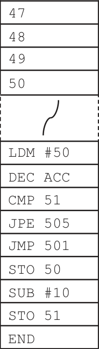
(i) Trace the program currently in memory using the following trace table. 3 marks
| Instruction address | ACC | Memory address | |||
|---|---|---|---|---|---|
| Instruction address | ACC | 50 | 51 | 52 | 53 |
| 47 | 48 | 49 | 50 | ||
(ii) Complete the table by identifying and describing two modes of addressing that are not used in the program in part (a). 4 marks
| Mode of addressing | Description |
|---|---|
(b) The table shows part of the instruction set for a processor. The processor has one register: 2 marks
the Accumulator (ACC).
| Instruction | Explanation | |
|---|---|---|
| Opcode | Operand | Operand |
| AND | #n/Bn/&n | Bitwise AND operation of the contents of ACC with the operand |
| AND | Bitwise AND operation of the contents of ACC with the contents of |
|
| XOR | #n/Bn/&n | Bitwise XOR operation of the contents of ACC with the operand |
| XOR | Bitwise XOR operation of the contents of ACC with the contents of |
|
| OR | #n/Bn/&n | Bitwise OR operation of the contents of ACC with the operand |
| OR | Bitwise OR operation of the contents of ACC with the contents of |
|
| can be an absolute or a symbolic address # denotes a denary number, e.g. #123 B denotes a binary number, e.g. B01001010 & denotes a hexadecimal number, e.g. &4A |
can be an absolute or a symbolic address # denotes a denary number, e.g. #123 B denotes a binary number, e.g. B01001010 & denotes a hexadecimal number, e.g. &4A |
can be an absolute or a symbolic address # denotes a denary number, e.g. #123 B denotes a binary number, e.g. B01001010 & denotes a hexadecimal number, e.g. &4A |
Write the bit manipulation instructions that can be used to set only the most significant bit to 1 in an 8-bit register.
The instructions need to work on a register that contains any 8-bit binary number.
Show mark scheme
5(a)(i) [3 marks]
1 mark for each shaded section Instruction Memory address address ACC 50 51 52 53 47 48 49 50 500 50 501 49 502 504 501 48 502 503 505 48 506 38 507 38
5(a)(ii) [4 marks]
1 mark for addressing mode, 1 mark for matching description • Direct • The operand is the address of the data • Indirect • The operand points to the memory location which is the address of the data • Indexed • The address of the data is formed by adding the contents of the Index Register (IX) to the operand
5(b) [2 marks]
1 mark for each correct instruction e.g. AND B00000000 / #0 / &0 OR B10000000 / #128 / &80
The following table shows part of the instruction set for a processor. The processor has two registers, the Accumulator (ACC) and the Index Register (IX).
| Instruction | Explanation | |
|---|---|---|
| Opcode | Operand | Operand |
| LDM | #n | Immediate addressing. Load the number n to ACC |
| LDD | Direct addressing. Load the contents of the location at the given address to ACC |
|
| LDI | Indirect addressing. The address to be used is at the given address. Load the contents of this second address to ACC |
|
| LDX | Indexed addressing. Form the address from + the contents of the index register. Copy the contents of this calculated address to ACC |
|
| LDR | #n | Immediate addressing. Load the number n to IX |
| ADD | #n/Bn/&n | Add the number n to the ACC |
| ADD | Add the contents of the given address to the ACC | |
| SUB | #n/Bn/&n | Subtract the number n from the ACC |
| SUB | Subtract the contents of the given address from the ACC | |
| INC | Add 1 to the contents of the register (ACC or IX) | |
| DEC | Subtract 1 from the contents of the register (ACC or IX) | |
| can be an absolute or a symbolic address # denotes a denary number, e.g. #123 B denotes a binary number, e.g. B01001010 & denotes a hexadecimal number, e.g. &4A |
can be an absolute or a symbolic address # denotes a denary number, e.g. #123 B denotes a binary number, e.g. B01001010 & denotes a hexadecimal number, e.g. &4A |
can be an absolute or a symbolic address # denotes a denary number, e.g. #123 B denotes a binary number, e.g. B01001010 & denotes a hexadecimal number, e.g. &4A |
(a) The current contents of memory are shown: 5 marks
Address Data
19 25
20 23
21 2
22 4
23 15
24 50
25 22
The current contents of the ACC and IX are shown:
ACC 50
IX 20
Complete the table by writing the content of the ACC and the IX after each set of instructions has run.
| Instructions | ACC content | IX content | |
|---|---|---|---|
| 1 | LDM #19 DEC ACC |
||
| 2 | LDD 23 ADD 19 |
||
| 3 | LDI 25 INC ACC |
||
| 4 | LDR #21 LDX 2 |
(b) The instruction set also includes these bit manipulation instructions:
| Instruction | Explanation | |
|---|---|---|
| Opcode | Operand | Operand |
| AND | #n/Bn/&n | Bitwise AND operation of the contents of ACC with the operand |
| AND | Bitwise AND operation of the contents of ACC with the contents of |
|
| XOR | #n/Bn/&n | Bitwise XOR operation of the contents of ACC with the operand |
| XOR | Bitwise XOR operation of the contents of ACC with the contents of |
|
| OR | #n/Bn/&n | Bitwise OR operation of the contents of ACC with the operand |
| OR | Bitwise OR operation of the contents of ACC with the contents of |
|
| LSL | #n | Bits in ACC are shifted logically n places to the left. Zeros are introduced on the right-hand end |
| LSR | #n | Bits in ACC are shifted logically n places to the right. Zeros are introduced on the left-hand end. |
| can be an absolute or a symbolic address # denotes a denary number, e.g. #123 B denotes a binary number, e.g. B01001010 & denotes a hexadecimal number, e.g. &4A |
can be an absolute or a symbolic address # denotes a denary number, e.g. #123 B denotes a binary number, e.g. B01001010 & denotes a hexadecimal number, e.g. &4A |
can be an absolute or a symbolic address # denotes a denary number, e.g. #123 B denotes a binary number, e.g. B01001010 & denotes a hexadecimal number, e.g. &4A |
The current content of the ACC is shown:
ACC 1 0 0 1 1 0 1 0
(i) The table has three sets of instructions. The binary number 10011010 is reloaded into the ACC before each set of instructions is run. 3 marks
Complete the table by writing the content of the ACC after each set of instructions has run.
| Instructions | ACC content | |
|---|---|---|
| 1 | LSL #2 | |
| 2 | ADD #5 AND #30 |
|
| 3 | OR B11110010 INC ACC |
(ii) Explain how bit manipulation can be used to test whether the binary number stored in the ACC represents an odd denary number. 3 marks
Write the bit manipulation instruction that will be used.
Explanation
Instruction
Show mark scheme
8(a) [5 marks]
1 mark for each correct content of the ACC (4) 1 mark for correct IX column Instructions ACC content IX content LDM #19 1 18 20 DEC ACC LDD 23 2 40 20 ADD 19 LDI 25 3 5 20 INC ACC LDR #21 4 15 21 LDX 2
8(b)(i) [3 marks]
1 mark each correct content of ACC Instructions ACC content LSL #2 1 0110 1000 ADD #5 2 0001 1110 AND #30 OR B11110010 3 1111 1011 INC ACC
8(b)(ii) [3 marks]
1 mark each to max 2 for explanation • An odd binary number will have a 1 in the Least Significant Bit (LSB) • A bit manipulation operation is required to access/mask only the LSB and clear all the others • Compare the result of the masking with denary 1 • … the result of the comparison will be true if the number is odd 1 mark for correct instruction • AND B00000001 // AND #1 // AND &01
The following table shows part of the instruction set for a processor. The processor has two registers, the Accumulator (ACC) and the Index Register (IX).
| Instruction | Explanation | |
|---|---|---|
| Opcode | Operand | Operand |
| LDM | #n | Immediate addressing. Load the number n to ACC |
| LDD | Direct addressing. Load the contents of the location at the given address to ACC |
|
| LDI | Indirect addressing. The address to be used is at the given address. Load the contents of this second address to ACC |
|
| LDX | Indexed addressing. Form the address from + the contents of the index register. Copy the contents of this calculated address to ACC |
|
| LDR | #n | Immediate addressing. Load the number n to IX |
| ADD | #n/Bn/&n | Add the number n to the ACC |
| ADD | Add the contents of the given address to the ACC | |
| SUB | #n/Bn/&n | Subtract the number n from the ACC |
| SUB | Subtract the contents of the given address from the ACC | |
| INC | Add 1 to the contents of the register (ACC or IX) | |
| DEC | Subtract 1 from the contents of the register (ACC or IX) | |
| can be an absolute or a symbolic address # denotes a denary number, e.g. #123 B denotes a binary number, e.g. B01001010 & denotes a hexadecimal number, e.g. &4A |
can be an absolute or a symbolic address # denotes a denary number, e.g. #123 B denotes a binary number, e.g. B01001010 & denotes a hexadecimal number, e.g. &4A |
can be an absolute or a symbolic address # denotes a denary number, e.g. #123 B denotes a binary number, e.g. B01001010 & denotes a hexadecimal number, e.g. &4A |
(a) The current contents of memory are shown: 3 marks
Address Data
50 54
51 55
52 50
53 52
54 100
55 25
56 50
The current contents of the ACC and IX are shown:
ACC 50
IX 45
Complete the table by writing the content of the ACC after each program has run.
| Instructions | ACC content | |
|---|---|---|
| 1 | LDD 50 ADD #4 ADD 54 |
|
| 2 | LDI 53 DEC ACC ADD 56 |
|
| 3 | LDM #55 SUB #5 |
(b) The instruction set also includes these bit manipulation instructions: 3 marks
| Instruction | Explanation | |
|---|---|---|
| Opcode | Operand | Operand |
| AND | #n/Bn/&n | Bitwise AND operation of the contents of ACC with the operand |
| AND | Bitwise AND operation of the contents of ACC with the contents of |
|
| XOR | #n/Bn/&n | Bitwise XOR operation of the contents of ACC with the operand |
| XOR | Bitwise XOR operation of the contents of ACC with the contents of |
|
| OR | #n/Bn/&n | Bitwise OR operation of the contents of ACC with the operand |
| OR | Bitwise OR operation of the contents of ACC with the contents of |
|
| can be an absolute or a symbolic address # denotes a denary number, e.g. #123 B denotes a binary number, e.g. B01001010 & denotes a hexadecimal number, e.g. &4A |
can be an absolute or a symbolic address # denotes a denary number, e.g. #123 B denotes a binary number, e.g. B01001010 & denotes a hexadecimal number, e.g. &4A |
can be an absolute or a symbolic address # denotes a denary number, e.g. #123 B denotes a binary number, e.g. B01001010 & denotes a hexadecimal number, e.g. &4A |
Explain how bit manipulation can be used to clear the data in an 8-bit register.
Write the bit manipulation instruction that will be used.
Explanation
Instruction
Show mark scheme
7(a) [3 marks]
1 mark each: Instructions ACC content LDD 50 ADD #4 1 158 ADD 54 LDI 53 DEC ACC 2 99 ADD 56 LDM #55 3 50 SUB #5
7(b) [3 marks]
1 mark for each bullet point for the explanation 1 mark for correct instruction • A bit manipulation operation is required to set all the bits to zero • Compare the result of the masking with 0 • … the result of comparison will be true if the register is cleared • AND B00000000 / #00 / &00
The following table shows part of the instruction set for a processor. The processor has two registers: the Accumulator (ACC) and an Index Register (IX).
| Instruction | Explanation | |
|---|---|---|
| Opcode | Operand | Operand |
LDM |
#n |
Immediate addressing. Load the number n to ACC |
LDD |
<address> |
Direct addressing. Load the contents of the location at the given address to ACC |
LDI |
<address> |
Indirect addressing. The address to be used is at the given address. Load the contents of this second address to ACC |
LDX |
<address> |
Indexed addressing. Form the address from + the contents of the Index Register. Copy the contents of this calculated address to ACC |
LDR |
#n |
Immediate addressing. Load the number n to IX |
ADD |
#n/Bn/&n |
Add the number n to the ACC |
ADD |
<address> |
Add the contents of the given address to the ACC |
SUB |
#n/Bn/&n |
Subtract the number n from the ACC |
SUB |
<address> |
Subtract the contents of the given address from the ACC |
INC |
<register> |
Add 1 to the contents of the register (ACC or IX) |
| can be an absolute or a symbolic address # denotes a denary number, e.g. #123 B denotes a binary number, e.g. B01001010 & denotes a hexadecimal number, e.g. &4A |
can be an absolute or a symbolic address # denotes a denary number, e.g. #123 B denotes a binary number, e.g. B01001010 & denotes a hexadecimal number, e.g. &4A |
can be an absolute or a symbolic address # denotes a denary number, e.g. #123 B denotes a binary number, e.g. B01001010 & denotes a hexadecimal number, e.g. &4A |
(a) The current contents of memory are shown: 4 marks 3 marks
Address Data
19 24
20 2
21 1
22 3
23 5
24 4
25 22
The current contents of the ACC and IX are shown:
ACC 12
IX 1
Complete the table by writing the content of the ACC after each program has run.
| Program number | Code | ACC content |
|---|---|---|
| 1 | LDD 20ADD #2 |
|
| 2 | LDX 22 |
|
| 3 | LDI 25INC ACCSUB 22 |
|
| 4 | LDD 19LDM #5LDM #25 |
|
| (b) The processor incl | ludes these bit manipulation instructions: | |
| --- | --- | --- |
| Instruction | Instruction | Explanation |
| Opcode | Operand | Operand |
AND |
#n/Bn/&n |
Bitwise AND operation of the contents of ACC with the operand |
AND |
<address> |
Bitwise AND operation of the contents of ACC with the contents of |
XOR |
#n/Bn/&n |
Bitwise XOR operation of the contents of ACC with the operand |
XOR |
<address> |
Bitwise XOR operation of the contents of ACC with the contents of |
OR |
#n/Bn/&n |
Bitwise OR operation of the contents of ACC with the operand |
OR |
<address> |
Bitwise OR operation of the contents of ACC with the contents of |
| can be an absolute or a symbolic address # denotes a denary number, e.g. #123 B denotes a binary number, e.g. B01001010 & denotes a hexadecimal number, e.g. &4A |
can be an absolute or a symbolic address # denotes a denary number, e.g. #123 B denotes a binary number, e.g. B01001010 & denotes a hexadecimal number, e.g. &4A |
can be an absolute or a symbolic address # denotes a denary number, e.g. #123 B denotes a binary number, e.g. B01001010 & denotes a hexadecimal number, e.g. &4A |
The current contents of memory are shown:
Address Data
        30 01110101
        31 11111111
        32 00000000
        33 11001100
        34 10101010
The current content of the ACC is shown:
1 0 0 1 1 0 1 0
Complete the table by writing the content of the ACC after each program has run.
The binary number 10011010 is reloaded into the ACC before each program is run.
| Program number | Code | ACC content |
|---|---|---|
| 1 | AND 31 |
|
| 2 | XOR B01001111 |
|
| 3 | OR #30 |
Show mark scheme
4(a) [4 marks]
1 mark for each correct answer: Program Code ACC Number Content LDD 20 1 4 ADD #2 LDX 22 2 5 LDI 25 3 1 INC ACC SUB 22 LDD 19 4 25 LDM #5 LDM #25
4(b) [3 marks]
1 mark for each correct answer: Program Code ACC Content Number AND 31 1 1001 1010 XOR B01001111 2 1101 0101 OR #30 3 1001 1110
The following table shows part of the instruction set for a processor. The processor has two registers: the Accumulator (ACC) and an Index Register (IX).
| Instruction | Explanation | |
|---|---|---|
| Opcode | Operand | Operand |
LDM |
#n |
Immediate addressing. Load the number n to ACC |
LDD |
<address> |
Direct addressing. Load the contents of the location at the given address to ACC |
LDI |
<address> |
Indirect addressing. The address to be used is at the given address. Load the contents of this second address to ACC |
LDX |
<address> |
Indexed addressing. Form the address from + the contents of the index register. Copy the contents of this calculated address to ACC |
LDR |
#n |
Immediate addressing. Load the number n to IX |
ADD |
#n/Bn/&n |
Add the number n to the ACC |
ADD |
<address> |
Add the contents of the given address to the ACC |
SUB |
#n/Bn/&n |
Subtract the number n from the ACC |
SUB |
<address> |
Subtract the contents of the given address from the ACC |
INC |
<register> |
Add 1 to the contents of the register (ACC or IX) |
| can be an absolute or a symbolic address # denotes a denary number, e.g. #123 B denotes a binary number, e.g. B01001010 & denotes a hexadecimal number, e.g. &4A |
can be an absolute or a symbolic address # denotes a denary number, e.g. #123 B denotes a binary number, e.g. B01001010 & denotes a hexadecimal number, e.g. &4A |
can be an absolute or a symbolic address # denotes a denary number, e.g. #123 B denotes a binary number, e.g. B01001010 & denotes a hexadecimal number, e.g. &4A |
(a) The current contents of memory are shown: 4 marks 3 marks
Address Data
10 1
11 3
12 5
13 11
14 10
15 16
16 12
The current contents of the ACC and IX are shown:
ACC 10
IX 0
Complete the table by writing the content of the ACC after each program has run.
| Program number | Code | ACC content |
|---|---|---|
| 1 | LDI 15SUB #1 |
|
| 2 | LDD 14ADD 11 |
|
| 3 | LDM #11ADD #3SUB 16 |
|
| 4 | LDR #2LDX 14ADD #2 |
|
| (b) The processor inclu | udes these bit manipulation instructions: | |
| --- | --- | --- |
| Instruction | Instruction | Explanation |
| Opcode | Operand | Operand |
AND |
#n/Bn/&n |
Bitwise AND operation of the contents of ACC with the operand |
AND |
<address> |
Bitwise AND operation of the contents of ACC with the contents of |
XOR |
#n/Bn/&n |
Bitwise XOR operation of the contents of ACC with the operand |
XOR |
<address> |
Bitwise XOR operation of the contents of ACC with the contents of |
OR |
#n/Bn/&n |
Bitwise OR operation of the contents of ACC with the operand |
OR |
<address> |
Bitwise OR operation of the contents of ACC with the contents of |
| can be an absolute or a symbolic address # denotes a denary number, e.g. #123 B denotes a binary number, e.g. B01001010 & denotes a hexadecimal number, e.g. &4A |
can be an absolute or a symbolic address # denotes a denary number, e.g. #123 B denotes a binary number, e.g. B01001010 & denotes a hexadecimal number, e.g. &4A |
can be an absolute or a symbolic address # denotes a denary number, e.g. #123 B denotes a binary number, e.g. B01001010 & denotes a hexadecimal number, e.g. &4A |
The current contents of memory are shown:
Address Data
25 11000110
26 11100001
27 10000001
28 11001101
29 00001111
The current content of the ACC is shown:
0 1 0 0 0 1 1 0
Complete the table by writing the content of the ACC after each program has run.
The binary number 01000110 is reloaded into the ACC before each program is run.
| Program number | Code | ACC content |
|---|---|---|
| 1 | XOR 29 |
|
| 2 | AND #29 |
|
| 3 | OR B11111111 |
Show mark scheme
5(a) [4 marks]
1 mark for each correct answer: Program Code ACC Content Number 1 LDI 15 11 SUB #1 2 LDD 14 13 ADD 11 2 3 LDM #11 ADD #3 SUB 16 4 LDR #2 14 LDX 14 ADD #2
5(b) [3 marks]
1 mark for each correct answer: Program Code ACC Content Number 1 XOR 29 0100 1001 2 AND #29 0000 0100 3 OR B11111111 1111 1111
The following table shows part of the instruction set for a processor. The processor has two registers: the Accumulator (ACC) and an Index Register (IX).
| Instruction | Explanation | |
|---|---|---|
| Opcode | Operand | Operand |
| LDM | #n | Immediate addressing. Load the number n to ACC |
| LDD | Direct addressing. Load the contents of the location at the given address to ACC |
|
| LDI | Indirect addressing. The address to be used is at the given address. Load the contents of this second address to ACC |
|
| LDX | Indexed addressing. Form the address from + the contents of the index register. Copy the contents of this calculated address to ACC |
|
| LDR | #n | Immediate addressing. Load the number n to IX |
| ADD | #n/Bn/&n | Add the number n to the ACC |
| ADD | Add the contents of the given address to the ACC | |
| DEC | Subtract 1 from the contents of the register (ACC or IX) | |
| SUB | #n/Bn/&n | Subtract the number n from the ACC |
| SUB | Subtract the contents of the given address from the ACC | |
| INC | Add 1 to the contents of the register (ACC or IX) | |
| can be an absolute or a symbolic address # denotes a denary number, e.g. #123 B denotes a binary number, e.g. B01001010 & denotes a hexadecimal number, e.g. &4A |
can be an absolute or a symbolic address # denotes a denary number, e.g. #123 B denotes a binary number, e.g. B01001010 & denotes a hexadecimal number, e.g. &4A |
can be an absolute or a symbolic address # denotes a denary number, e.g. #123 B denotes a binary number, e.g. B01001010 & denotes a hexadecimal number, e.g. &4A |
Show mark scheme
3(a) [4 marks]
1 mark for each correct answer: Program Code ACC Number Content LDM #50 1 50 INC ACC SUB #1 LDI 51 2 97 ADD 52 LDR #2 3 48 LDX 50 DEC ACC LDD 52 4 44 SUB 54 INC ACC
3(b) [3 marks]
1 mark for each correct answer: Instruction Instruction ACC Content Number LSL #2 1 1111 1100 XOR 100 2 1111 0010 AND 103 3 0011 0111
(a) Identify the purpose of the first pass of a two-pass assembler. 1 mark
(b) The following table shows part of the instruction set for a processor. The processor has two registers, the Accumulator (ACC) and the Index Register (IX).
| Instruction | Explanation | |
|---|---|---|
| Opcode | Operand | Operand |
LDR |
#n |
Immediate addressing. Load the number n to IX |
STO |
<address> |
Store contents of ACC at the given address |
ADD |
<address> |
Add the contents of the given address to the ACC |
INC |
<register> |
Add 1 to the contents of the register (ACC or IX) |
CMP |
#n |
Compare the contents of ACC with number n |
JPE |
<address> |
Following a compare instruction, jump to if the compare was True |
OUT |
Output to the screen the character whose ASCII value is stored in ACC | |
| can be an absolute or symbolic address # denotes a denary number, e.g. #123 |
can be an absolute or symbolic address # denotes a denary number, e.g. #123 |
can be an absolute or symbolic address # denotes a denary number, e.g. #123 |
(i) Give one example of an instruction that belongs to each of the following instruction groups. 3 marks
Only use the instructions given in the table. Each instruction must have a suitable operand.
Data movement
Arithmetic operation
Conditional instruction
(ii) The instruction LDR #2 uses immediate addressing. 2 marks
Give one similarity and one difference between direct addressing and indexed addressing.
Similarity
Difference
(iii) Identify one other mode of addressing. 1 mark
(c) The following table shows another part of the instruction set for the same processor.
| Instruction | Explanation | |
|---|---|---|
| Opcode | Operand | Operand |
AND |
Bn |
Bitwise AND operation of the contents of ACC with the operand |
XOR |
Bn |
Bitwise XOR operation of the contents of ACC with the operand |
LSR |
#n |
Bits in ACC are shifted logically n places to the right. Zeros are introduced on the left hand end |
| # denotes a denary number, e.g. #123 B denotes a binary number, e.g. B01001101 |
# denotes a denary number, e.g. #123 B denotes a binary number, e.g. B01001101 |
# denotes a denary number, e.g. #123 B denotes a binary number, e.g. B01001101 |
(i) The current contents of the ACC are: 1 mark
0 1 0 0 1 1 1 1
Show the contents of the ACC after the execution of the following instruction.
AND B10100101
(ii) The current contents of the ACC are: 1 mark
0 0 0 1 0 1 1 1
Show the contents of the ACC after the execution of the following instruction.
LSR #3
(iii) The current contents of the ACC are: 1 mark
1 1 1 1 0 1 1 1
Show the contents of the ACC after the execution of the following instruction.
XOR B00100101
Show mark scheme
8(a) [1 mark]
1 mark for: • To create a symbol table
8(b)(i) [3 marks]
1 mark for each bullet point • Data movement: e.g. LDR #50 // STO 201 • Arithmetic operation: e.g. ADD 100 // INC IX • Conditional instruction: e.g. JPE 96
8(b)(ii) [2 marks]
1 mark for each bullet point ( max 2 ) Similarity: • both load the contents of an address into the Accumulator Difference: • direct accesses the address given by the operand whereas indexed adds the contents of IX to the operand and accesses the data at that calculated address
8(b)(iii) [1 mark]
1 mark for • Indirect (addressing) • Relative (addressing)
8(c)(i) [1 mark]
0000 0101
8(c)(ii) [1 mark]
0000 0010
8(c)(iii) [1 mark]
1101 0010
The following table shows part of the instruction set for a processor. The processor has two registers, the Accumulator (ACC) and the Index Register (IX).
| Instruction | Explanation | |
|---|---|---|
| Opcode | Operand | Operand |
LDD |
<address> |
Direct addressing. Load the contents of the location at the given address to ACC |
LDX |
<address> |
Indexed addressing. Form the address from + the contents of the index register. Copy the contents of this calculated address to ACC |
LDR |
#n |
Immediate addressing. Load the number n to IX |
STO |
<address> |
Store the contents of ACC at the given address |
ADD |
#n |
Add the denary number n to the ACC |
JMP |
<address> |
Jump to the given address |
INC |
<register> |
Add 1 to the contents of the register (ACC or IX) |
CMP |
<address> |
Compare the contents of ACC with the contents of |
CMI |
<address> |
Indirect addressing. The address to be used is at the given address. Compare the contents of ACC with the contents of this second address |
JPE |
<address> |
Following a compare instruction, jump to if the compare was True |
IN |
Key in a character and store its ASCII value in ACC | |
OUT |
Output to the screen the character whose ASCII value is stored in ACC |
|
END |
Return control to the operating system | |
| can be an absolute or a symbolic address # denotes a denary number, e.g. #123 |
can be an absolute or a symbolic address # denotes a denary number, e.g. #123 |
can be an absolute or a symbolic address # denotes a denary number, e.g. #123 |
(a) The instructions in the processor’s instruction set can be grouped according to their function. 4 marks
Identify the instruction group for each of the following opcodes.
IN
ADD
JPE
CMI
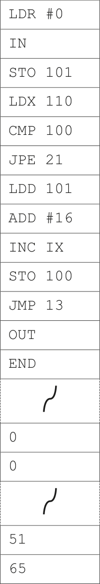
(b) The current contents of main memory and selected values from the ASCII character set are given on page 15. 4 marks
Trace the program currently in memory using the trace table when the input is ‘1’.
Address Instruction
...
...
| 15 | |||||||
|---|---|---|---|---|---|---|---|
| Instruction address |
ACC | IX | Memory address | Memory address | Memory address | Memory address | Output |
| Instruction address |
ACC | IX | 100 | 101 | 110 | 111 | |
0 |
0 |
51 |
65 |
||||
| ASCII value | Character | ||||||
| --- | --- | ||||||
| 49 | 1 | ||||||
| 50 | 2 | ||||||
| 51 | 3 | ||||||
| 52 | 4 | ||||||
| ... | |||||||
| 65 | A | ||||||
| 66 | B | ||||||
| 67 | C | ||||||
| 68 | D |
Show mark scheme
9(a) [4 marks]
1 mark for each bullet point •
- Input and output of data IN •
- Arithmetic operations ADD •
- Unconditional and conditional instructions JPE •
- Compare instructions CMI
9(b) [4 marks]
1 mark for each set of shaded rows Memory address Output Instruction ACC IX address 100 101 110 111 0 0 51 65 10 0 11 49 12 49 13 51 14 15 16 49 17 65 18 1 19 65 20 13 65 14 15 21 A 22
A program is written in assembly language.
(a) The program is converted into machine code by a two‑pass assembler.
Draw one or more lines to identify the pass or passes in which each action takes place.
Action
generates object code
reads the source code one line at a time
removes white space
adds labels to the symbol table
(b) Assembly language statements can use different modes of addressing. 3 marks 3 marks
Complete the following description of addressing modes.
Pass
first
second ______ addressing is when the operand holds the memory address of
the data.
______ addressing is when the operand holds a memory address that
stores the memory address of the data.
______ addressing is when the operand is the data.
Show mark scheme
3(a) [3 marks]
1 mark for generates object code to second pass 1 mark for reads source code one line at a time to both boxes 1 mark for removes white space and adds labels to first pass Action Pass generates object code first reads the source code one line at a time removes white space second adds labels to the symbol table
3(b)
1 mark for each correct term Direct addressing is when the operand holds the memory address of the data. Indirect addressing is when the operand holds a memory address that stores the memory address of the data. Immediate addressing is when the operand is the data.
A photographer creates a relational database to store data about photographs taken at birthday parties.
The database, PHOTOGRAPHS, stores details of the customer, the party, the photographs taken
and the cameras used.
The photographer has several cameras that are used for taking the photographs at the parties.
Each camera has a specific lens type (for example, XY32Z) and lighting type (for example, F1672).
Data about each photograph is stored in the database including the party at which it was taken, the time it was taken and the camera used.
The database has these four tables:
  CUSTOMER(CustomerID, FirstName, LastName, Telephone)
  PARTY(PartyID, CustomerID, PartyDate, StartTime)
  PHOTO_DATA(PhotoID, PartyID, TimeTaken, CameraID)
  CAMERA_DATA(CameraID, LensType, LightingType)
(a) Complete the entity-relationship (E-R) diagram for the database PHOTOGRAPHS .
PARTY CUSTOMER PHOTO_DATA CAMERA_DATA 3 marks
Show mark scheme
4(a) [3 marks]
1 mark for each correct relationship: • 1:M between CUSTOMER and PARTY • 1:M between PARTY and PHOTO_DATA • 1:M between CAMERA_DATA and PHOTO_DATA CUSTOMER PARTY PHOTO_DATA CAMERA_DATA
4(b) [3 marks]
1 mark for each bullet point ( max 3 ): • no repeating groups of attributes // data is atomic • no partial key dependencies • no non-key dependencies // no transitive dependencies
4(c)(i) [2 marks]
1 mark for the definition, 1 mark for the example: • definition: a single row in a table • example: from the table PHOTO_DATA
4(c)(ii) [4 marks]
1 mark for each correctly completed empty space: • COUNT • PhotoID • PHOTO_DATA • 'CAN*' // ‘CAN%’ SELECT COUNT ( PhotoID ) FROM PHOTO_DATA WHERE CameraID LIKE ' CAN* '; // WHERE CameraID LIKE ' CAN% ';
4(d) [3 marks]
1 mark for each bullet point: • ALTER TABLE CAMERA_DATA • ADD NumberStored INTEGER • , LastUsed DATE; ALTER TABLE CAMERA_DATA ADD NumberStored INTEGER, LastUsed DATE;
(a) The table shows part of the instruction set for a processor. The processor has one general purpose register, the Accumulator (ACC). 3 marks
| Instruction | Explanation | |
|---|---|---|
| Opcode | Operand | Operand |
LDM |
#n |
Immediate addressing. Load the number n to ACC |
LDD |
<address> |
Direct addressing. Load the contents of the location at the given address to ACC |
LDI |
<address> |
Indirect addressing. The address to be used is at the given address. Load the contents of this second address to ACC |
| can be an absolute or symbolic address # denotes a denary number, e.g. #123 |
can be an absolute or symbolic address # denotes a denary number, e.g. #123 |
can be an absolute or symbolic address # denotes a denary number, e.g. #123 |
The current contents of main memory are:
Address
100 101
101 67
102 104
103 100
104 68
| Complete the table by writi instruction. | ing the value stored in the |
|---|---|
| Instruction | Accumulator |
LDM #103 |
|
LDD 102 |
|
LDI 103 |
Show mark scheme
3(a) [3 marks]
1 mark for each correct value Instruction Accumulator LDM #103 103 LDD 102 104 LDI 103 101
3(b) [4 marks]
1 mark for group name, 1 mark for appropriate description e.g. Input and output of data Takes an input from the user // outputs the character of the binary number Arithmetic operations Perform addition and subtraction Unconditional and conditional instructions Move to another instruction (identified by a label) Compare instructions Compare the result to another value
3(c) [3 marks]
1 mark for each correct line Instruction Result 01111101 XOR 11110000 00111101 OR 01010101 11111111 AND 11111111 11000010 11001101
(a) There are two errors in the following register transfer notation for the fetch‑execute cycle. 4 marks
1 MAR [PC]
2 PC [PC] − 1
      3 MDR  [MAR]
      4 CIR  [MDR]
Complete the following table by:
identifying the line number of each error
describing the error
writing the correct statement.
Line
numberDescription of the error Correct statement
(b) The following table shows part of the instruction set for a processor. The processor has one general purpose register, the Accumulator (ACC), and an Index Register (IX). 4 marks
| Instruction | Explanation | |
|---|---|---|
| Opcode | Operand | Operand |
LDM |
#n |
Immediate addressing. Load the number n to ACC |
LDD |
<address> |
Direct addressing. Load the contents of the location at the given address to ACC |
STO |
<address> |
Store the contents of ACC at the given address |
INC |
<register> |
Add 1 to the contents of the register (ACC or IX) |
CMP |
<address> |
Compare the contents of ACC with the contents of |
JPN |
<address> |
Following a compare instruction, jump to if the compare was False |
JMP |
<address> |
Jump to the given address |
IN |
Key in a character and store its ASCII value in ACC | |
OUT |
Output to the screen the character whose ASCII value is stored in ACC | |
END |
Return control to the operating system | |
XOR |
#n |
Bitwise XOR operation of the contents of ACC with the operand |
XOR |
<address> |
Bitwise XOR operation of the contents of ACC with the contents of |
AND |
#n |
Bitwise AND operation of the contents of ACC with the operand |
AND |
<address> |
Bitwise AND operation of the contents of ACC with the contents of |
OR |
#n |
Bitwise OR operation of the contents of ACC with the operand |
OR |
<address> |
Bitwise OR operation of the contents of ACC with the contents of |
LSL |
#n |
Bits in ACC are shifted logically n places to the left. Zeros are introduced on the right hand end |
LSR |
#n |
Bits in ACC are shifted logically n places to the right. Zeros are introduced on the left hand end |
| can be an absolute or symbolic address # denotes a denary number, e.g. #123 B denotes a binary number, e.g. B01001101 |
can be an absolute or symbolic address # denotes a denary number, e.g. #123 B denotes a binary number, e.g. B01001101 |
can be an absolute or symbolic address # denotes a denary number, e.g. #123 B denotes a binary number, e.g. B01001101 |
The current contents of main memory are shown:
Address Data
        100 00001111
        101 11110000
        102 01010101
        103 11111111
        104 00000000
Each row of the following table shows the current contents of ACC in binary and the instruction that will be performed on those contents.
| Complete the table by w instruction. | writing the new contents of the A | ACC after the execution of each |
|---|---|---|
| Current contents of the ACC | Instruction | New contents of the ACC |
11111111 |
OR 101 |
|
00000000 |
XOR #15 |
|
10101010 |
LSR #2 |
|
01010101 |
AND 104 |
Show mark scheme
6(a) [4 marks]
1 mark for identification of line and description of error 1 mark for the correct statement Line Description of the error Correct statement number 2 Program Counter should be incremented, ← PC [PC] + 1 not decremented 3 It should be the contents of the address in ← MDR [[MAR]] the MAR
6(b) [2 marks]
1 mark for each correct row Current contents of the ACC Instruction New contents of the ACC 11111111 OR 101 11111111 00000000 XOR #15 00001111 10101010 LSR #2 00101010 01010101 AND 104 00000000
The Von Neumann model for a computer system uses registers.
(a) Describe the role of the following special purpose registers in the fetch-execute (F-E) cycle.
(i) Memory Address Register (MAR) 4 marks
Memory Data Register (MDR)
(ii) Another special purpose register is the Index Register. 1 mark
Identify one other special purpose register used in the Von Neumann model for a computer system.
(b) The following table shows part of the instruction set for a processor. The processor has one general purpose register, the Accumulator (ACC), and an Index Register (IX).
| Instruction | Explanation | |
|---|---|---|
| Opcode | Operand | Operand |
LDM |
#n |
Immediate addressing. Load the number n to ACC |
LDD |
<address> |
Direct addressing. Load the contents of the location at the given address to ACC |
STO |
<address> |
Store the contents of ACC at the given address |
INC |
<register> |
Add 1 to the contents of the register (ACC or IX) |
CMP |
<address> |
Compare the contents of ACC with the contents of |
JPN |
<address> |
Following a compare instruction, jump to if the compare was False |
JMP |
<address> |
Jump to the given address |
IN |
Key in a character and store its ASCII value in ACC | |
OUT |
Output to the screen the character whose ASCII value is stored in ACC | |
END |
Return control to the operating system | |
XOR |
#n |
Bitwise XOR operation of the contents of ACC with the operand |
XOR |
<address> |
Bitwise XOR operation of the contents of ACC with the contents of |
OR |
#n |
Bitwise OR operation of the contents of ACC with the operand |
OR |
<address> |
Bitwise OR operation of the contents of ACC with the contents of |
AND |
#n |
Bitwise AND operation of the contents of ACC with the operand |
AND |
<address> |
Bitwise AND operation of the contents of ACC with the contents of |
LSL |
#n |
Bits in ACC are shifted logically n places to the left. Zeros are introduced on the right hand end |
LSR |
#n |
Bits in ACC are shifted logically n places to the right. Zeros are introduced on the left hand end |
| can be an absolute or symbolic address # denotes a denary number, e.g. #123 |
can be an absolute or symbolic address # denotes a denary number, e.g. #123 |
can be an absolute or symbolic address # denotes a denary number, e.g. #123 |
The current contents of main memory are shown:
Address Data
        100 01010101
        101 11110000
        102 00001111
        103 00000000
        104 11111111
(i) In the following table, each row shows the current contents of the ACC in binary and the instruction that will be performed on those contents. 4 marks
| Complete the table instruction. | by writing the new contents of the | e ACC after the execution of each |
|---|---|---|
| Current contents of the ACC | Instruction | New contents of the ACC |
01010101 |
XOR 101 |
|
11110000 |
AND 104 |
|
00001111 |
LSL #4 |
|
11111111 |
OR 102 |
(ii) The following table contains five assembly language instruction groups. 4 marks
Write an appropriate assembly language instruction for each instruction group, using the given instruction set. The first one has been completed for you.
| Instruction Group | Instruction |
|---|---|
| Data movement | LDM #2 |
| Input and output of data | |
| Arithmetic operations | |
| Unconditional and conditional instructions | |
| Compare instructions |
(iii) The opcode LDM uses immediate addressing. The opcode LDD uses direct addressing. 2 marks
Identify and describe one additional mode of addressing.
Mode of addressing
Description
Show mark scheme
8(a)(i) [1 mark]
1 mark for each bullet point to max 2 for each register MAR Stores the next address to be fetched • ... held in the Program Counter (PC) • The data at this address is then fetched • MDR Stores the data from the address pointed to by the MAR • The data in it is copied to the Current Instruction Register (CIR) •
8(a)(ii)
1 mark for a correct register e.g. Program Counter (PC) Current Instruction Register (CIR) Status register Interrupt register
8(b)(i) [4 marks]
1 mark for each correct answer Current contents of New contents of Instruction the ACC the ACC 01010101 XOR 101 1010 0101 11110000 AND 104 1111 0000 00001111 LSL #4 1111 0000 11111111 OR 102 1111 1111
8(b)(ii) [4 marks]
1 mark for each correct instruction Instruction Group Instruction Data movement LDM #2 Input and output of data IN / OUT Arithmetic Operations INC ACC / INC IX Unconditional and conditional instructions JPN 100 / JMP 100 Compare instructions CMP 100
8(b)(iii) [2 marks]
1 mark for name, 1 mark for description Indirect addressing • the address to be used is at the given address • Relative addressing • the address to be used is an offset number of locations away, relative to • the address of the current instruction Indexed addressing • form the address from the given address plus the contents of the index • register
(a) There are two errors in the following register transfer notation for the fetch‑execute cycle. 4 marks
1 MAR [PC]
2 PC [PC] − 1
      3 MDR  [MAR]
      4 CIR  [MDR]
Complete the following table by:
identifying the line number of each error
describing the error
writing the correct statement.
Line
numberDescription of the error Correct statement
(b) The following table shows part of the instruction set for a processor. The processor has one general purpose register, the Accumulator (ACC), and an Index Register (IX). 4 marks
| Instruction | Explanation | |
|---|---|---|
| Opcode | Operand | Operand |
LDM |
#n |
Immediate addressing. Load the number n to ACC |
LDD |
<address> |
Direct addressing. Load the contents of the location at the given address to ACC |
STO |
<address> |
Store the contents of ACC at the given address |
INC |
<register> |
Add 1 to the contents of the register (ACC or IX) |
CMP |
<address> |
Compare the contents of ACC with the contents of |
JPN |
<address> |
Following a compare instruction, jump to if the compare was False |
JMP |
<address> |
Jump to the given address |
IN |
Key in a character and store its ASCII value in ACC | |
OUT |
Output to the screen the character whose ASCII value is stored in ACC | |
END |
Return control to the operating system | |
XOR |
#n |
Bitwise XOR operation of the contents of ACC with the operand |
XOR |
<address> |
Bitwise XOR operation of the contents of ACC with the contents of |
AND |
#n |
Bitwise AND operation of the contents of ACC with the operand |
AND |
<address> |
Bitwise AND operation of the contents of ACC with the contents of |
OR |
#n |
Bitwise OR operation of the contents of ACC with the operand |
OR |
<address> |
Bitwise OR operation of the contents of ACC with the contents of |
LSL |
#n |
Bits in ACC are shifted logically n places to the left. Zeros are introduced on the right hand end |
LSR |
#n |
Bits in ACC are shifted logically n places to the right. Zeros are introduced on the left hand end |
| can be an absolute or symbolic address # denotes a denary number, e.g. #123 B denotes a binary number, e.g. B01001101 |
can be an absolute or symbolic address # denotes a denary number, e.g. #123 B denotes a binary number, e.g. B01001101 |
can be an absolute or symbolic address # denotes a denary number, e.g. #123 B denotes a binary number, e.g. B01001101 |
The current contents of main memory are shown:
Address Data
        100 00001111
        101 11110000
        102 01010101
        103 11111111
        104 00000000
Each row of the following table shows the current contents of ACC in binary and the instruction that will be performed on those contents.
| Complete the table by w instruction. | writing the new contents of the A | ACC after the execution of each |
|---|---|---|
| Current contents of the ACC | Instruction | New contents of the ACC |
11111111 |
OR 101 |
|
00000000 |
XOR #15 |
|
10101010 |
LSR #2 |
|
01010101 |
AND 104 |
Show mark scheme
6(a) [4 marks]
1 mark for identification of line and description of error 1 mark for the correct statement Line Description of the error Correct statement number 2 Program Counter should be incremented, ← PC [PC] + 1 not decremented 3 It should be the contents of the address in ← MDR [[MAR]] the MAR
6(b) [2 marks]
1 mark for each correct row Current contents of the ACC Instruction New contents of the ACC 11111111 OR 101 11111111 00000000 XOR #15 00001111 10101010 LSR #2 00101010 01010101 AND 104 00000000
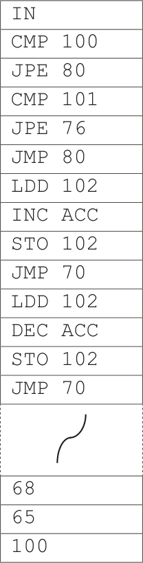
The current contents of the main memory and selected values from the ASCII character set are shown.
Address Instruction ASCII code table (selected codes only)

| ASCII code | Character |
|---|---|
65 |
A |
66 |
B |
67 |
C |
68 |
D |
…
Complete the trace table for the program currently in main memory. 6 marks
| Instruction address |
ACC | Memory address | IX | Output | |||
|---|---|---|---|---|---|---|---|
| Instruction address |
ACC | 365 |
366 |
367 |
368 |
368 |
368 |
1 |
3 |
65 |
66 |
0 |
|||
(c) (i) The Accumulator currently contains the binary number:
0 0 1 1 0 1 0 1 Write the contents of the Accumulator after the processor has executed the following instruction:
LSL #2 1 mark
(ii) The Accumulator currently contains the binary number:
0 0 1 1 0 1 0 1 Identify the mathematical operation that the following instruction will perform on the contents of the accumulator.
LSR #3 1 mark
Show mark scheme
8 [3 marks]
1 mark per correct row Statement AND NAND NOR XOR OR The output is 1 only when both inputs are 1 The output is 1 only when both inputs are different The output is 1 only when both inputs are 0
The table shows part of the instruction set for a processor. The processor has one general purpose register, the Accumulator (ACC), and an Index Register (IX).
| Instruction | Explanation | |
|---|---|---|
| Opcode | Operand | Operand |
LDM |
#n |
Immediate addressing. Load the number n to ACC |
LDD |
<address> |
Direct addressing. Load the contents of the location at the given address to ACC |
STO |
<address> |
Store contents of ACC at the given address |
ADD |
<address> |
Add the contents of the given address to the ACC |
INC |
<register> |
Add 1 to the contents of the register (ACC or IX) |
DEC |
<register> |
Subtract 1 from the contents of the register (ACC or IX) |
CMP |
<address> |
Compare the contents of ACC with the contents of |
JPE |
<address> |
Following a compare instruction, jump to if the compare was True |
JPN |
<address> |
Following a compare instruction, jump to if the compare was False |
JMP |
<address> |
Jump to the given address |
IN |
Key in a character and store its ASCII value in ACC | |
OUT |
Output to the screen the character whose ASCII value is stored in ACC | |
END |
Return control to the operating system | |
| # denotes a denary number, e.g. #123 | # denotes a denary number, e.g. #123 | # denotes a denary number, e.g. #123 |
The current contents of the main memory and selected values from the ASCII character set are:
Address Instruction ASCII code table (selected codes only)
     …

|ASCII code|Character|
|---|---|
|`65`<br>|`A`<br>|
|`66`<br>|`B`<br>|
|`67`<br>|`C`<br>|
|`68`|`D`|
Show mark scheme
4(a) [4 marks]
1 mark for each shaded section / bullet point Load 65 into ACC • Load 100 into ACC, increment and store in 102 • Load 68 into ACC • Load 101 into ACC, decrement and store in 102 • Memory address Instruction ACC address 100 101 102 68 65 100 70 65 71 72 73 74 76 100 77 101 78 101 79 70 68 71 72 80 101 81 100 82 100 83 (70)
4(b)(i) [1 mark]
102
4(b)(ii) [1 mark]
AND
4(b)(iii) [5 marks]
1 mark for AND, 1 mark for #15 AND #15
The current contents of the main memory and selected values from the ASCII character set are shown.
Address Instruction ASCII code table (selected codes only)
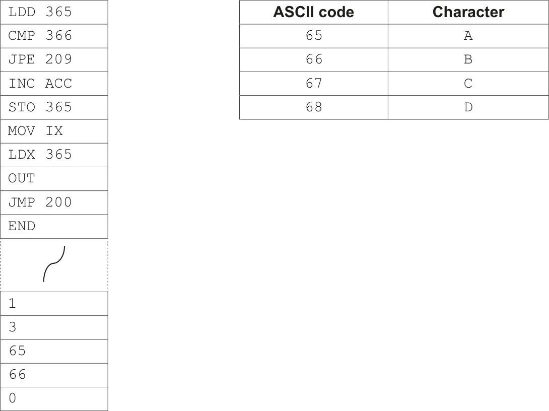
| ASCII code | Character |
|---|---|
65 |
A |
66 |
B |
67 |
C |
68 |
D |
…
Complete the trace table for the program currently in main memory. 6 marks
| Instruction address |
ACC | Memory address | IX | Output | |||
|---|---|---|---|---|---|---|---|
| Instruction address |
ACC | 365 |
366 |
367 |
368 |
368 |
368 |
1 |
3 |
65 |
66 |
0 |
|||
(c) (i) The Accumulator currently contains the binary number:
0 0 1 1 0 1 0 1 Write the contents of the Accumulator after the processor has executed the following instruction:
LSL #2 1 mark
(ii) The Accumulator currently contains the binary number:
0 0 1 1 0 1 0 1 Identify the mathematical operation that the following instruction will perform on the contents of the accumulator.
LSR #3 1 mark
Show mark scheme
8 [3 marks]
1 mark per correct row Statement AND NAND NOR XOR OR The output is 1 only when both inputs are 1 The output is 1 only when both inputs are different The output is 1 only when both inputs are 0